burner

A combustion device and burner technology, applied in combustion chambers, combustion methods, combustion equipment, etc., can solve the problems of unobtainable, difficult to reduce fan noise, and inability to fully reduce the passage resistance of combustion exhaust, so as to reduce fan noise, Effect of Resonance Noise Reduction

Active Publication Date: 2016-03-23
RINNAI CORP
View PDF5 Cites 0 Cited by
  • Summary
  • Abstract
  • Description
  • Claims
  • Application Information

AI Technical Summary

Problems solved by technology

[0008] However, if the cross-sectional area of ​​the exhaust restriction cylinder is not sufficiently reduced, the above-mentioned effects cannot be obtained.
Therefore, even in this combustion device, the passage resistance of the combustion exhaust gas cannot be sufficiently reduced, and it is difficult to reduce the fan noise.

Method used


Image

  • burner
  • burner
  • burner

Examples


Embodiment Construction

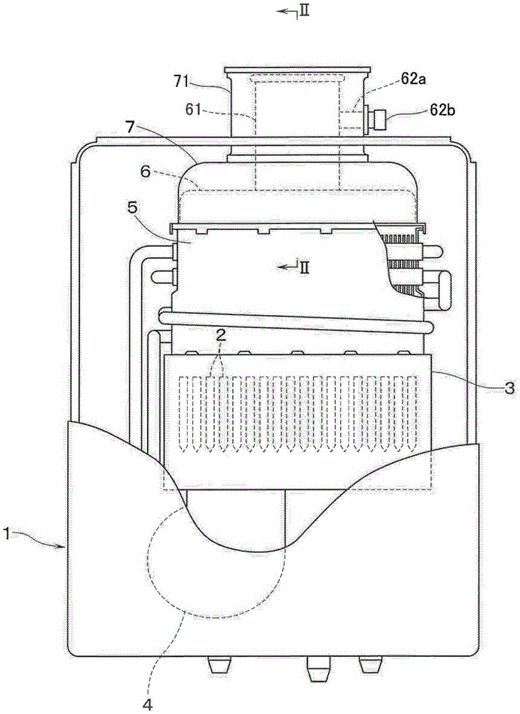
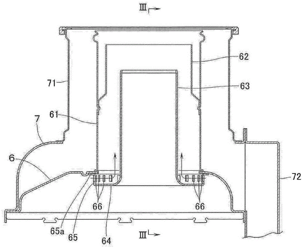
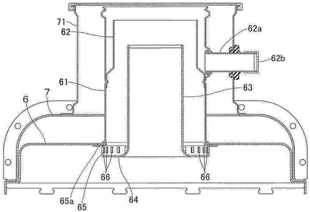
[0019] figure 1 A combustion device composed of a heat source device for water supply installed indoors is shown. This combustion device includes an exterior case 1 . Disposed in the outer casing 1 are: a combustion frame 3 with a plurality of rich-lean combustion type burners 2 built in; a fan 4 below the combustion frame 3; a heat exchanger 5 for water supply above the combustion frame 3; a heat exchanger 5 above the exhaust hood 6; and the exhaust hood 6 covered air supply hood 7. And, utilize the fan 4 via the air supply hood 7 and the air supply pipe 72 connected with the air supply hood 7 (refer to figure 2 ) sucks outside air from an air supply tube extending outside (not shown), and supplies the outside air as combustion air into the combustion frame 3 . Combustion exhaust gas from the burner 2 flows from the combustion frame 3 to the heat exchanger 5 and heats the outside air. Then, the combustion exhaust gas passing through the heat exchanger 5 flows into the ex...


PUM


Abstract

The invention provides a combustion device comprising a combustion frame provided with a combustor therein, a fan supplying air for combustion into the combustion frame, a heat exchanger disposed above the combustion frame and an exhaust hood arranged above the heat exchanger. Combustion exhaust is discharged via a barrel-shaped exhaust port extending from the upper wall portion of the exhaust hood to the top. The combustion device comprises an exhaust restricting barrel (63) which is inserted to the exhaust port from the bottom. The combustion device has the advantages that the fan noise can be reduced and Helmholtz resonance noise can also be reduced. A barrel part (632) erecting towards the top is formed on the periphery of an annular flange part (631) extending from the lower end of the exhaust restricting barrel (63) to the radial outside. The upper end of the barrel part (632) is fixed to an opening edge of the exhaust port in the upper wall portion of the exhaust hood. A plurality of ventilation holes (633) allowing the combustion exhaust to pass through are arranged in the barrel part circumferentially in a spaced manner.

Description

technical field [0001] The present invention relates to a combustion device, which comprises: a combustion frame with a built-in burner; a fan, which supplies combustion air into the combustion frame; and a heat exchanger, which is arranged in the combustion frame. above and is heated by the combustion exhaust from the burner. Background technique [0002] Conventionally, this type of combustion device has an exhaust hood, which is arranged above the heat exchanger, and the combustion exhaust gas that has passed through the heat exchanger flows into the exhaust hood, and the combustion exhaust gas passes through the upper wall of the exhaust hood. A cylindrical exhaust port extending upward, and an exhaust tube connected to the exhaust port, are discharged to the outside. [0003] However, as described above, Helmholtz-type resonance occurs in a combustion device including a combustion frame, a heat exchanger, and an exhaust hood. Assuming that the internal volume from the...

Claims


Application Information

Patent Timeline
Patent Type & Authority Patents(China)
IPC IPC(8): F23J13/00
CPCF23J13/02F23J2213/10F23L17/02F23M9/003
Inventor 小代卓史
Owner RINNAI CORP
Why Eureka
Try Eureka