
Method and device for high-tension switch cabinet gas detection

A high-voltage switchgear, gas detection technology, applied in measuring devices, instruments, scientific instruments, etc., can solve problems such as inability to accurately measure operating temperature, insufficient accuracy, and inability to obtain test components

Inactive Publication Date: 2013-06-12
WENZHOU ELECTRIC POWER BUREAU +2
View PDF3 Cites 19 Cited by
  • Summary
  • Abstract
  • Description
  • Claims
  • Application Information

AI Technical Summary

Problems solved by technology

[0004] 1. It is controlled by the operating state of the high-voltage switchgear during the detection, such as real-time monitoring of electric power parameters (voltage, current, electric power), for the switchgear that does not perform breaking and closing actions for a long time, it is impossible to obtain the corresponding test components , so it is not suitable for switch cabinets that do not perform breaking and closing actions for a long time
[0005] 2. The detection is easily affected by the external test conditions, resulting in insufficient measurement accuracy
For example, the use of electromagnetic waves to monitor the partial discharge of switchgear is susceptible to interference from external strong electromagnetic fields; while the method of infrared imaging is affected by the closed structure of the system and cannot accurately measure the operating temperature

Method used


Image

  • Method and device for high-tension switch cabinet gas detection
  • Method and device for high-tension switch cabinet gas detection
  • Method and device for high-tension switch cabinet gas detection

Examples


Embodiment 1

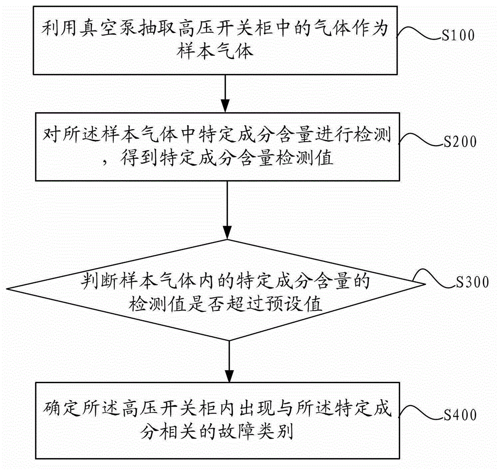
[0054] figure 1 It is a schematic flowchart of the method for detecting gas in a high-voltage switchgear provided in the embodiment of the present application.

[0055] Such as figure 1 As shown, the method includes:

[0056] S100: Using a vacuum pump to extract gas in the high-voltage switchgear as a sample gas.

[0057] When there is a fault in the high-voltage switchgear, the fault here includes: contact overheating, partial discharge, SF6 leakage, etc., the gas composition in the high-voltage switchgear will change, for example: after partial discharge, it will cause ozone in the gas The amount increases; and when the contacts are overheated, the concentration of particulate matter in the air will increase.

[0058] Therefore, analyzing the gas in the high-voltage switchgear can be used as a means of fault detection.

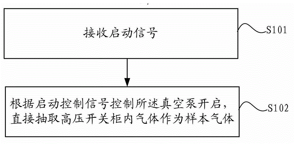
[0059] In addition, in the embodiment of the present application, when the vacuum pump is located inside the high-voltage switchgear, such as figure 2...

Embodiment 2

[0085] Figure 5 It is a schematic structural diagram of a gas detection device for a high-voltage switchgear provided in an embodiment of the present application.

[0086] Such as Figure 5 As shown, A in the figure is a high-voltage switchgear, and the gas detection device includes: a gas acquisition unit 10, a gas channel 20, a gas sensor 30, a judgment unit 40 and a fault category determination unit 50, wherein:

[0087] The gas acquisition unit 10 communicates with the space in the high-voltage switchgear, and is used to extract the gas in the high-voltage switchgear as a sample gas, and deliver the sample gas into the gas channel 20 .

[0088] In the embodiment of this application, as Figure 5 As shown, the gas acquisition unit 10 may include: a signal receiving unit 11, a vacuum pump 12 and an exhaust pipeline 13, wherein:

[0089] A signal receiving unit 11, configured to receive a start control signal, and send the start control signal to the vacuum pump;

[0090...


PUM


Abstract

The invention discloses a method and a device for high-tension switch cabinet gas detection. The method includes that gas in a high-tension switch cabinet is extracted through a vacuum pump to serve as sample gas; the sample gas is conveyed into a gas sensor, specific component contents in the sample gas are detected, and specific component content detection values are obtained; whether the specific component content detection values exceed preset values in the sample gas or not is judged; and when a judgment result is yes, fault categories related with specific components generated in the high-tension switch cabinet are determined. Compared with the prior art, according to the method, the principle that gas components in the high-tension switch cabinet can produce corresponding changes when the high-tension switch cabinet breaks down is utilized, and further through analysis on the gas components in the high-tension switch cabinet, the faults of the high-tension switch cabinet can be detected. In addition, due to the fact that the faults are detected through the gas components, the detection can be carried out just through the fact that a pump-out pipeline is connected on the high-tension switch cabinet, and operating states of the high-tension switch cabinet do not affect the detection.

Description

technical field [0001] The present application relates to the technical field of high-voltage equipment detection, in particular to a method and device for detecting gas in a high-voltage switchgear. Background technique [0002] In the power system, the high-voltage switchgear is responsible for the dual functions of closing and disconnecting the power lines and protecting the safety of the system. With the rapid development of the power system towards high voltage, large units, and large capacity, the power grid is expanding day by day and the unattended management of substations With the popularization and promotion of mode and comprehensive automation, the safe operation of high-voltage switchgear is becoming more and more important. When the switch blade contacts in the high-voltage switchgear and the joints of the power cable inlet and outlet lines are in poor contact, the contact resistance will increase, and heat will be generated when the load current flows. Overhea...

Claims


Application Information

Patent Timeline
IPC IPC(8): G01N33/00
Inventor 陈炯鲍克勤陈达季凌武林群陈植林剑黄继来王禾兴李勇经纲亮刘冲张海龙吴德峰金建新
Owner WENZHOU ELECTRIC POWER BUREAU
Learn More