Permanent magnet synchronous motor rotor permanent magnet temperature detection device and method

A technology of temperature detection device and permanent magnet synchronization, which is applied in the direction of electromechanical devices, electric components, electrical components, etc., can solve the problems of large contact resistance changes, low communication reliability, and low reliability, and achieve motor protection and real-time non-contact The effect of detecting the temperature of the permanent magnet of the rotor

Inactive Publication Date: 2020-03-13
ZHUHAI ENPOWER ELECTRIC
View PDF6 Cites 4 Cited by
  • Summary
  • Abstract
  • Description
  • Claims
  • Application Information

AI Technical Summary

Problems solved by technology

[0008] 2. The measurement method includes two methods of contact temperature measurement and non-contact temperature measurement: 1) The contact temperature measurement method embeds a temperature sensor inside the rotor, and leads out the temperature signal through a specific signal transmission method. Mechanical slip rings or wireless transmission technologies such as infrared, bluetooth, etc., if this method transmits temperature signals through mechanical slip rings, the reli

Method used


Image

  • Permanent magnet synchronous motor rotor permanent magnet temperature detection device and method
  • Permanent magnet synchronous motor rotor permanent magnet temperature detection device and method
  • Permanent magnet synchronous motor rotor permanent magnet temperature detection device and method

Examples


Embodiment Construction

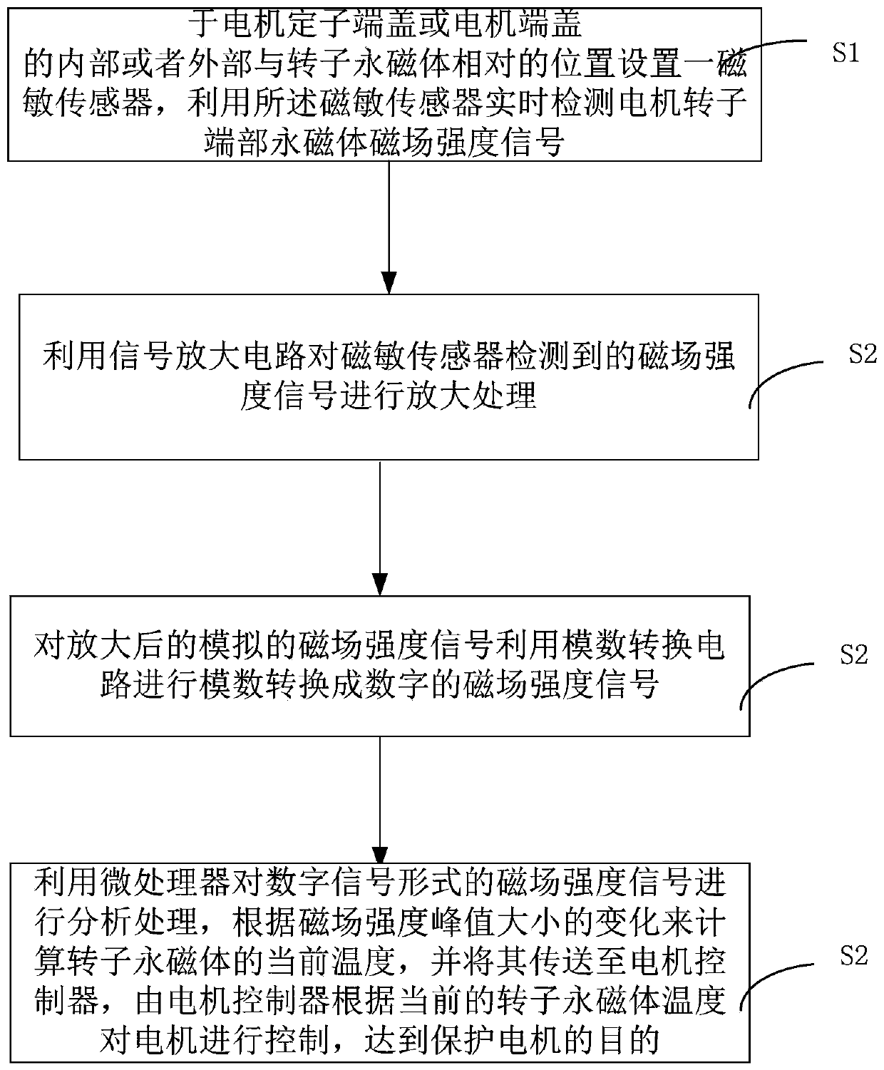
[0035] The implementation of the present invention is described below through specific examples and in conjunction with the accompanying drawings, and those skilled in the art can easily understand other advantages and effects of the present invention from the content disclosed in this specification. The present invention can also be implemented or applied through other different specific examples, and various modifications and changes can be made to the details in this specification based on different viewpoints and applications without departing from the spirit of the present invention.

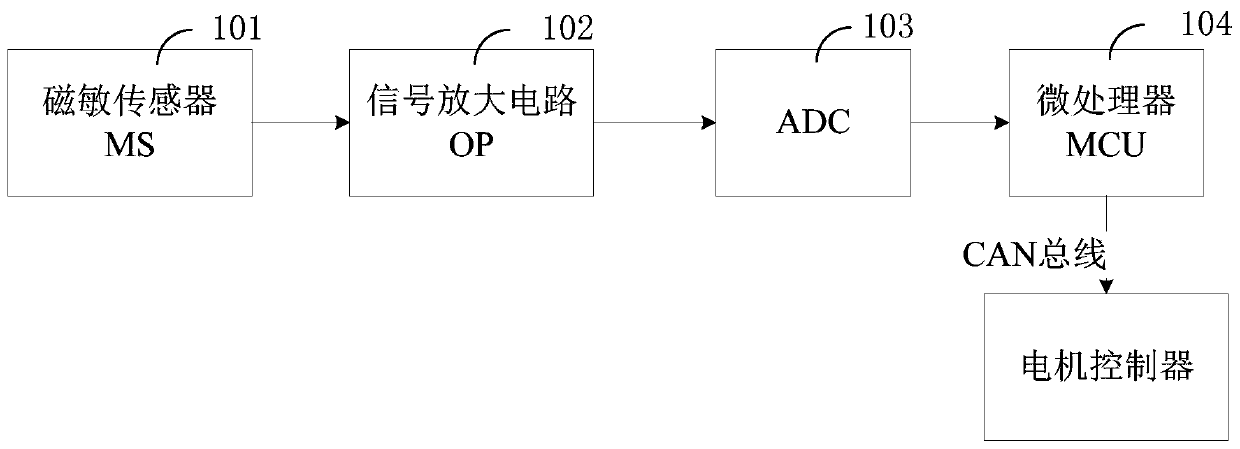
[0036] figure 1 It is a structural schematic diagram of a permanent magnet temperature detection device for a permanent magnet synchronous motor rotor of the present invention. Such as figure 1 As shown, a permanent magnet synchronous motor rotor permanent magnet temperature detection device of the present invention comprises:

[0037] The magnetic sensitive sensor 101 is arranged on the ...


PUM


Abstract

The invention discloses a permanent magnet synchronous motor rotor permanent magnet temperature detection device and method, and the device comprises a magneto-dependent sensor which is disposed at aposition, opposite to a rotor permanent magnet, inside or outside a motor stator end cover or a motor end cover, and is used for the real-time detection of a magnetic field intensity signal of the permanent magnet at the end part of a motor rotor; a signal amplification circuit used for amplifying the magnetic field intensity signal detected by the magneto-dependent sensor; an analog-to-digital conversion circuit used for carrying out analog-to-digital conversion on the analog magnetic field intensity signal amplified by the signal amplification circuit to obtain a digital magnetic field intensity signal; and a microprocessor used for analyzing and processing the magnetic field intensity signal in the form of the digital signal, calculating the current temperature of the rotor permanentmagnet according to the change of the peak value of the magnetic field intensity and transmitting the current temperature to the motor controller, wherein the motor controller controls the motor according to the current temperature of the rotor permanent magnet, so that the purpose of protecting the motor is achieved.

Description

technical field [0001] The invention relates to the technical field of motors, in particular to a permanent magnet temperature detection device and method for a permanent magnet synchronous motor rotor. Background technique [0002] Permanent magnet synchronous motor (English name is permanent magnet synchronous motor, referred to as PMSM) is mainly composed of rotor, end cover and stator. The stator structure of the permanent magnet synchronous motor is very similar to the structure of the ordinary induction motor. The biggest difference between the rotor structure and the asynchronous motor is that there are high-quality permanent magnet poles on the rotor. According to the position of the permanent magnet on the rotor, Permanent magnet synchronous motors are generally divided into surface rotor structures and built-in rotor structures. [0003] Generally speaking, for high-safety motors such as long-running equipment or locomotives, controlling temperature rise is very n...

Claims


Application Information

Patent Timeline
IPC IPC(8): H02K11/25
CPCH02K11/25
Inventor 刘宏鑫魏标王国锋仲玉龙
Owner ZHUHAI ENPOWER ELECTRIC
Why Eureka
Try Eureka