Liquid crystal module structure

A liquid crystal module and backlight module technology, which is applied in nonlinear optics, instruments, optics, etc., can solve the problems affecting the display area effect and instability of the liquid crystal display device, and achieve the purpose of avoiding uneven black borders and ensuring the display effect. Effect

Active Publication Date: 2013-06-12
SHENZHEN CHINA STAR OPTOELECTRONICS TECH CO LTD
View PDF6 Cites 14 Cited by
  • Summary
  • Abstract
  • Description
  • Claims
  • Application Information

AI Technical Summary

Problems solved by technology

When using the existing liquid crystal module structure to assemble a liquid crystal display device, the liquid crystal display panel 500 is assembled on the backlight module 100 (such as image 3 As shown), due to assembly tolerance factors, the liquid crystal display panel 500 will be left or right, up or down against the backlight module 100, and when the front frame 700 is covered, the black matrix 508 of the liquid crystal display panel 500 is exposed to the The width of the opening of the front frame 700 is unstable due to the deflection of the liquid crystal display panel 500, which in turn affects the effect of the display area of ​​the liquid crystal display device

Method used


Image

  • Liquid crystal module structure
  • Liquid crystal module structure
  • Liquid crystal module structure

Examples


Embodiment Construction

[0034] In order to further illustrate the technical means adopted by the present invention and its effects, the following describes in detail in conjunction with preferred embodiments of the present invention and accompanying drawings.

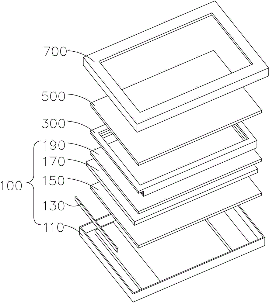
[0035] see Figure 4 to Figure 13 , the present invention provides a liquid crystal module structure, comprising: a backlight module 2, a plastic frame 4 mounted on the backlight module 2, a liquid crystal display panel 6 mounted on the plastic frame 4, a The adapter 8 and the front frame 9 installed on the adapter 8 .

[0036] The backlight module 2 includes a backplane 22, a light guide plate 24 disposed inside the backplane 22, a reflection sheet 26 disposed between the light guide plate 24 and the backplane 22, and an optical film set 28 disposed on the light guide plate 24. And the backlight 29 installed on the backboard 22 .

[0037] The back plate 22 includes a bottom plate 222 and a plurality of first side plates 224 vertically conne...


PUM


Abstract

The invention provides a liquid crystal module structure which comprises a backlight module, a rubber frame, a liquid crystal display panel, an adapter piece and a front frame, wherein the rubber frame is installed on the backlight module; the liquid crystal display panel is installed on the rubber frame; the adapter piece is installed on the backlight module; the front frame is installed on the adapter piece; and the adapter piece comprises a connecting plate and a positioning plate, wherein the positioning plate is vertically connected to the connecting plate, the connecting plate is installed on the backlight module, the liquid crystal display panel abuts on the positioning plate, and the front frame is fixedly connected to the positioning plate. According to the liquid crystal module structure, the adapter piece used for positioning the liquid crystal display panel is arranged, so that the distance between the edge of an opening of the front frame which is locked and installed on the adapter piece and the edge of a black matrix of the liquid crystal display panel is kept unchanged, thereby guaranteeing the stability of the width of the exposed black matrix when the liquid crystal display panel is assembled, and the phenomenon of uneven peripheral black edges of a display area due to instability of the width of the exposed black matrix because of the assembly tolerance of the liquid crystal display panel of a liquid crystal display device of the existing liquid crystal module structure is avoided.

Description

technical field [0001] The invention relates to the field of liquid crystal display, in particular to a liquid crystal module structure. Background technique [0002] A liquid crystal display (LCD, Liquid Crystal Display) has many advantages such as a thin body, power saving, and no radiation, and has been widely used. Most of the liquid crystal display devices currently on the market are backlight liquid crystal display devices, which include a housing, a liquid crystal panel disposed in the housing, and a backlight module disposed in the housing. The working principle of the liquid crystal panel is to place liquid crystal molecules between two parallel glass substrates, control the direction of the liquid crystal molecules by electrifying or not, and refract the light from the backlight module to produce a picture. Since the liquid crystal panel itself does not emit light, the light source provided by the backlight module is needed to display images normally. Therefore, t...

Claims


Application Information

Patent Timeline
Patent Type & Authority Applications(China)
IPC IPC(8): G02F1/13G02F1/1333G02F1/13357
CPCG02F1/133308
Inventor 黄冲萧宇均
Owner SHENZHEN CHINA STAR OPTOELECTRONICS TECH CO LTD
Why Eureka
Try Eureka