Alternating current rectifying circuit and alternating current rectifying method for driving light-emitting diode (LED) module

A technology of LED module and rectifier circuit, which is applied in the direction of electric lamp circuit arrangement, electric light source, lighting device, etc., can solve the problems of reducing the service life of the LED module, flickering of the LED module, and low stability of the output voltage, etc.

Active Publication Date: 2013-06-12
四川能投智慧光电有限公司
View PDF4 Cites 8 Cited by
  • Summary
  • Abstract
  • Description
  • Claims
  • Application Information

AI Technical Summary

Problems solved by technology

Therefore, in the existing AC rectification circuit, when the current loop turns, the voltage that can be provided to the external LED module is lower than the turn-on voltage, so that the luminous efficiency of the LED module is low; further, after rectification by the diode in the

Method used


Image

  • Alternating current rectifying circuit and alternating current rectifying method for driving light-emitting diode (LED) module
  • Alternating current rectifying circuit and alternating current rectifying method for driving light-emitting diode (LED) module
  • Alternating current rectifying circuit and alternating current rectifying method for driving light-emitting diode (LED) module

Examples


Example Embodiment

[0095] The technical solutions of the embodiments of the present invention will be clearly and completely described below in conjunction with the accompanying drawings. Obviously, the described embodiments are only a part of the embodiments of the present invention, rather than all the embodiments. Based on the embodiments of the present invention, all other embodiments obtained by those of ordinary skill in the art without creative work shall fall within the protection scope of the present invention.
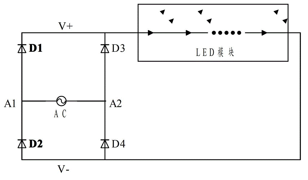
[0096] The existing AC power rectifier circuit for driving the LED module, because the AC power fluctuates periodically, and the LED module has a certain turn-on voltage. Therefore, when the current loop changes, the voltage that can be provided to the external LED module is less than the turn-on voltage, so that the LED The luminous efficiency of the module is low; further, after the rectification of the diode in the alternating current rectifier circuit, the voltage value output ...


PUM


Abstract

The invention discloses an alternating current rectifying circuit and an alternating current rectifying method for driving a light-emitting diode (LED) module. The method comprises that after an alternating current is rectified, and the rectified alternating current is output to a positive half cycle rectifying branch circuit of the LED module when an alternating current module is in a positive half cycle. When the alternating current module is in a negative half cycle, charging is carried out according to the alternating current output by the alternating current module, and when the alternating current module is in the positive half cycle, electro-discharge is carried out, and the alternating current is output to a negative half cycle rectifying branch circuit of the LED module. When the alternating current module is in the negative half cycle, the alternating current is rectified, and the alternating current is output to a positive half cycle rectifying branch circuit of the LED module. When the alternating current module is in the negative half cycle, the electro-discharge is carried out, and the alternating current is output to a negative half cycle feed branch circuit of the LED module. When an output voltage signal is higher than a preset voltage threshold value, an overvoltage protection branch circuit of the LED module is shut off. By means of the alternating current rectifying circuit, stability of output voltage can be improved, and luminous efficiency of the LED module is improved.

Description

technical field [0001] The invention relates to an alternating current rectification technology, in particular to an alternating current rectification circuit and an alternating current rectification method for driving a light emitting diode (LED, Light Emitting Diode) module. Background technique [0002] As a new high-efficiency light source, LED (Light Emitting Diode) module is widely used in lighting in commercial, industrial and household fields due to its advantages of long life, low energy consumption, energy saving and environmental protection. [0003] When the LED module is used as the light source of the lighting device, the life of the lighting device not only depends on the luminous performance of the LED, but also depends on the stability of the driving circuit components that provide the working voltage of the LED module. In the current application scheme, the bottleneck of LED module life is still the voltage stability provided by the driving circuit. In ord...

Claims


Application Information

Patent Timeline
IPC IPC(8): H05B37/02
Inventor 李东明封正勇龙文涛杨冕
Owner 四川能投智慧光电有限公司
Why Eureka
Try Eureka