Viscous clutch and method of operation thereof

A clutch, viscous technology, used in clutches, friction clutches, fluid clutches, etc., can solve problems, problems with viscous clutch valve tolerances, inability to provide good sealing against viscous fluids, etc.

Active Publication Date: 2016-09-28
HORTON
View PDF5 Cites 0 Cited by
  • Summary
  • Abstract
  • Description
  • Claims
  • Application Information

AI Technical Summary

Problems solved by technology

[0003] However, tolerances of known viscous clutch valves can be problematic, for example in terms of providing fluid-tight flatness of the valve components
For example, known valve assemblies that use a single pivoting valve stem that is not flat enough may not provide a good seal against viscous fluid flow from the reservoir into the working area
Furthermore, known solenoid control valve assemblies require a relatively large magnetic field for actuation (ie, to overcome erroneous spring bias), which would require an undesirably large solenoid
Large solenoid coils tend to be relatively heavy, expensive and energy-intensive

Method used


Image

  • Viscous clutch and method of operation thereof
  • Viscous clutch and method of operation thereof
  • Viscous clutch and method of operation thereof

Examples


Embodiment Construction

[0014] The present invention generally relates to a valve assembly suitable for use with a viscous clutch. For example, the valve assembly of the present invention is suitable for use with PCT Application No. PCT / US2010 / 056659, filed November 15, 2010, and U.S. Provisional Patent Application No. 61 / US2010, entitled "Integrated viscous clutch," filed November 17, 2009. 261,965, each of which is hereby incorporated by reference in its entirety. This application claims priority to US Provisional Patent Application No. 61 / 375,173, filed August 19, 2010, entitled "viscous clutch valve assembly," which is hereby incorporated by reference in its entirety.

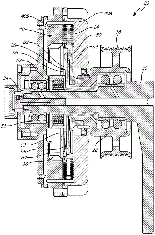
[0015] figure 1 is a cross-sectional view of one embodiment of a viscous clutch 20 comprising a solenoid assembly 22, a rotor 24, a valve assembly 26, a first support device 28, a shaft (or bracket) 30, a second support device 32, a retaining A member 34 , a reservoir 36 , an input member 38 (eg, a sheave), and an output member ...


PUM


Abstract

A valve assembly for a viscous clutch is disclosed, the valve assembly comprising: an orifice plate defining an aperture to allow fluid to pass through the orifice plate; a reed valve fixed relative to the orifice plate; including a magnetic flux conducting An armature of material; an anchor spring secured to the armature; and a reinforcing plate. The reed valve includes a tongue configured to selectively cover the aperture of the orifice plate and a first pivot location along the tongue. A second pivot position is defined along the anchor spring at the edge of the reinforcing plate. The first and second pivot positions are spaced apart from each other. The armature is configured to selectively apply force to the reed valve to pivot at least a portion of the tongue about the first pivot position.

Description

technical field [0001] The present invention relates generally to valves, and more particularly to electromagnetically actuated valves for use with viscous clutches. Background technique [0002] Viscous clutches are used in many applications, for example as fan drives in automotive applications. Clutches employ silicone oil to transmit torque between two rotating parts. Clutches may be engaged or disengaged by allowing the oil to enter and leave the operational area of ​​the clutch. Valves are used to control the flow of oil between the input rotor and output housing. More recent designs have incorporated allowing oil to be stored in the rotating input portion of the clutch while the clutch is disengaged in order to maintain kinetic energy available for quick engagement of the disengaged clutch. This also allows the clutch to have very low output fan speeds while in the disengaged position. This design also becomes common for clutches to be controlled electrically (ie e...

Claims


Application Information

Patent Timeline
Patent Type & Authority Patents(China)
IPC IPC(8): F16D48/02F16D25/08F16D13/58
CPCF16D35/024F16D25/08F16D35/028F16D48/02
Inventor 威廉·弗朗西斯·吉维尔斯德里克·萨维拉斯科特·米勒
Owner HORTON
Why Eureka
Try Eureka