Method and device for modulating and adjusting sending terminal and sending terminal

An adjustment method and adjustment device technology, applied in the direction of adjusting transmission rate, adjusting channel coding, digital transmission system, etc., can solve the problems of inaccurate SNR estimation, poor modulation adjustment effect, and inability to accurately reflect the change of noise, etc., to achieve Improve accuracy, improve the effect of transmission effect

Active Publication Date: 2013-06-12
HUAWEI TECH CO LTD
3 Cites 0 Cited by

AI-Extracted Technical Summary

Problems solved by technology

However, since the SNR estimation of the channel by the receiving end is not accurate and cannot accurately reflect the change of noise, t...

Method used

A plurality of sub-passages are divided into at least two groups again, each group of sub-passages comprises at least one sub-passage, the initial SNR margin SNR Margin of every group of sub-passages is different, the initial SNR of each sub-passage in a group of sub-passages Margins are the same. For example, each sub-channel is pre-numbered, respectively 1-8, and the 8 sub-channels are divided into four groups. The first group of sub-channels includes sub-channels numbered 1, 2, 5 and 6 respectively. The initial SNR Margin is 0db, the second group of sub-channels includes sub-channels numbered 3 and 7, the initial SNR Margin of the second group of sub-channels is 3db, the third group of sub-channels includes the sub-channel numbered 4, and the third The initial SNR Margin of the group sub-channel is 6db, the fourth group of sub-channels includes a sub-channel numbered 8, and the initial SNR Margin of the fourth group of sub-channels is 9db. The number of sub-channels with a smaller initial SNR Margin may be greater than the number of sub-channels with a larger initial SNR Margin, and sub-channels with different initial SNR Margins are arranged in a staggered manner to improve the transmission capability of the communication system.
In another implementation, for example, for example, the retransmission request rate of the first group of sub-channels whose initial SNR Margin is 0db is 100%, but the initial SNR Margin is respectively the second group of sub-channels of 3db, 6db and 9db, The retransmission request rates of the third group of subchannels and the fourth group of subchannels are both low. Since the retransmission request rate is different under different noise increase conditions, a proportional coefficient can be determined according to the retransmission request rate of the second group of sub-channels, and the product of the proportional coefficient and the initial SNRMargin of the second group of sub-channels As the noise increase amount, the accuracy of determining the noise increase amount is further improved.
The sending end modulation adjustment method provided by the present embodiment, the sending end modulation adjustment device determines the retransmission request rate of each group of sub-channels according to the retransmission requests received by at least two groups of sub-channels, and determines that the retransmission request rate is not 100% of at least one group of sub-channels, determining noise change information according to initial SNR margins of at least one group of sub-channels, and adjusting SNR margins of each sub-channel group of sub-channels according to sub-channel noise change information. Since the initial signal-to-noise ratio margin of each group of sub-channels is different, the noise change at th...

Abstract

The embodiment of the invention provides a method and device for modulating and adjusting a sending terminal and the sending terminal. The method for modulating and adjusting the sending terminal comprises the steps of determining the retransmission request rate of each set of sub-channels according to a received retransmission request rate via at least two sets of sub-channels, determining at least one set of sub-channel of which the retransmission request rate is not 100%; determining the noise change information according to an initial signal to noise ratio margin of the at least one set of sub-channel, and adjusting the signal to noise ratio margin of each set of sub-channel at a receiving terminal according to the noise change information at the receiving terminal. By the method and device for modulating and adjusting the sending terminal and the sending terminal, the accurate dynamic adjustment of the modulation parameters at the sending terminal is realized, and the transmission effect of a communication system is improved.

Application Domain

Technology Topic

Image

  • Method and device for modulating and adjusting sending terminal and sending terminal
  • Method and device for modulating and adjusting sending terminal and sending terminal
  • Method and device for modulating and adjusting sending terminal and sending terminal

Examples

  • Experimental program(1)

Example Embodiment

[0051] In order to make the objectives, technical solutions, and advantages of the embodiments of the present invention clearer, the technical solutions in the embodiments of the present invention will be described clearly and completely in conjunction with the accompanying drawings in the embodiments of the present invention. Obviously, the described embodiments It is a part of the embodiments of the present invention, not all the embodiments. Based on the embodiments of the present invention, all other embodiments obtained by those of ordinary skill in the art without creative work shall fall within the protection scope of the present invention.
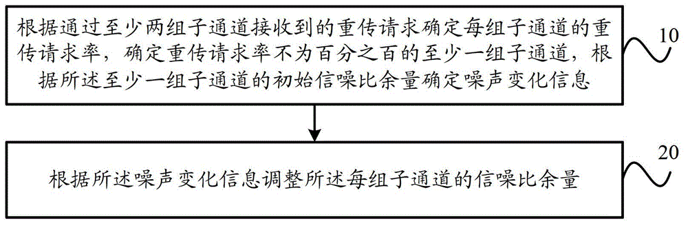
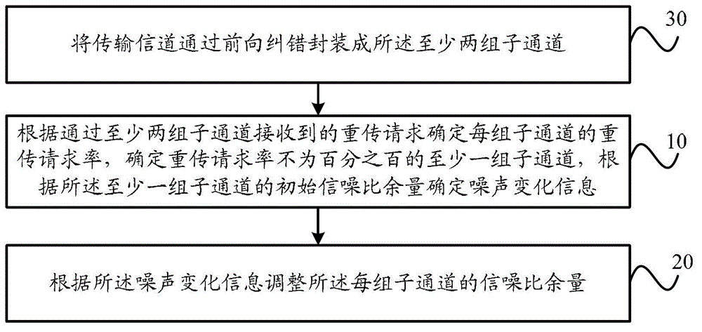
[0052] figure 1 This is a flowchart of a modulation adjustment method at a transmitting end according to an embodiment of the present invention. Such as figure 1 As shown, the modulation adjustment method at the transmitting end provided in this embodiment can be specifically applied to the dynamic adjustment process of the modulation parameter of the transmitting end in the communication system. The communication system may specifically be an OFDM (Orthogonal Frequency Division Multiplexing, Orthogonal Frequency Division Multiplexing) modulation and demodulation technology communication system, and may also be other communication systems that use multiple sub-channels for data transmission. The sending-end modulation adjustment method provided in this embodiment may be specifically executed by a sending-end modulation adjustment device, and the sending-end modulation adjustment device may be integrated in the sending end of the communication system.
[0053] The modulation adjustment method at the transmitting end provided in this embodiment specifically includes:
[0054] Step 10. Determine the retransmission request rate of each group of subchannels according to the retransmission requests received through at least two groups of subchannels, determine at least one group of subchannels whose retransmission request rate is not 100%, and determine according to the at least one group of subchannels The initial signal-to-noise ratio margin for determining noise change information, wherein each group of subchannels includes at least one subchannel, and the initial signal-to-noise ratio margin for each group of subchannels is different;
[0055] Step 20: Adjust the signal-to-noise ratio margin of each group of sub-channels according to the noise change information.
[0056] Specifically, the transmission channel of the communication system is pre-decomposed into multiple sub-channels, and the channel can be decomposed into multiple sub-channels. In the first implementation, if the communication system adopts OFDM modulation and demodulation technology, it can be According to the sub-carrier, the transmission channel is divided into multiple orthogonal sub-channels; in the second implementation mode, the transmission channel can be encapsulated into multiple logical sub-channels through FEC (Forward Error Correction); In the third implementation manner, a layered mapping method can also be used to decompose the transmission channel into multiple sub-channels. Decomposing the transmission channel into sub-channels can also be implemented in other ways, and is not limited to this embodiment.
[0057] The multiple sub-channels are then divided into at least two groups, each group of sub-channels includes at least one sub-channel, the initial SNR Margin of each group of sub-channels is different, and the initial SNR Margin of each sub-channel in a group of sub-channels is the same. For example, each sub-channel is pre-numbered, 1-8, 8 sub-channels are divided into four groups, the first group of sub-channels include sub-channels numbered 1, 2, 5, and 6, the first group of sub-channels The initial SNR Margin of the subchannel is 0db, the second group of subchannels includes subchannels numbered 3 and 7, the initial SNR Margin of the second group of subchannels is 3db, and the third group of subchannels includes the subchannel numbered 4. The initial SNR Margin of the group of subchannels is 6db, the fourth group of subchannels includes the subchannel numbered 8, and the initial SNR Margin of the fourth group of subchannels is 9db. The number of sub-channels with a smaller initial SNR Margin can be larger than the number of sub-channels with a larger initial SNR Margin, and the sub-channels with different initial SNR Margins are staggered to improve the transmission capacity of the communication system.
[0058] The modulation adjustment device at the transmitting end sets modulation parameters according to the initial SNR Margin, and sends data packets to the receiving end through each sub-channel. When the receiving end does not receive the data packet or the received data packet is wrong, it sends a retransmission request to the transmitting end. For each group of subchannels, the sender determines the retransmission request rate of the group of subchannels according to the retransmission request received by the group of subchannels, determines at least one group of subchannels whose retransmission request rate is not 100%, and then according to the retransmission The initial signal-to-noise ratio margin of at least one group of sub-channels whose request rate is not 100% determines noise change information, and the noise change information is specifically used to indicate the change of noise. The modulation adjustment device at the transmitting end adjusts the signal-to-noise ratio margin of each group of sub-channels according to the noise change information to realize the adjustment of the modulation parameters. There are several specific implementation methods:
[0059] In the first implementation, if the retransmission request rate of each group of subchannels is not 100%, and is less than a preset threshold, that is, the retransmission request rate of each group of subchannels is relatively small, indicating that the channel condition is good. There is no change in the noise, that is, the value of the noise change information is zero, and there is no need to adjust the modulation parameters, that is, each group of sub-channels maintains the initial SNR Margin.
[0060] In the second implementation, if the retransmission request rate of at least one set of subchannels is 100% or exceeds the preset threshold, but the retransmission request rate of the remaining subchannels is not high, it means that the noise at the receiving end has increased, and the noise has increased The amount is between the initial SNR Margin of the subchannel whose retransmission request rate is 100% and the initial SNR Margin of the subchannel whose retransmission request rate is not 100%. Then, preferably, the smallest initial SNRMargin among the subchannels whose retransmission request rate is not 100% or does not exceed the preset threshold can be directly determined as the noise increase. The noise increase is the noise change information, and the increase is increased according to the noise increase. The signal-to-noise ratio margin of each group of sub-channels.
[0061] In the third implementation, if the retransmission request rate of at least one set of subchannels exceeds 100% of the preset threshold, but the retransmission request rate of the remaining subchannels is not high, it means that the noise at the receiving end has increased, and the amount of noise increase Between the initial SNR Margin of the subchannel whose retransmission request rate is 100% and the initial SNR Margin of the subchannel whose retransmission request rate is not 100%. It can also determine the minimum initial SNR Margin among the sub-channels whose retransmission request rate is not 100% or does not exceed the preset threshold, and determine the scale factor according to the retransmission request rate of the sub-channel corresponding to the minimum initial SNR Margin. The initial SNR Margin is multiplied by the scale factor to obtain the noise increase. The noise increase is the noise change information, and the SNR margin of each group of sub-channels is increased according to the noise increase.
[0062] In the fourth implementation, if the retransmission request rate of each group of subchannels is not 100%, and the retransmission request rate of the group of subchannels with the smallest initial SNR Margin is relatively low, a minimum threshold can be set. If the transmission request rate is lower than the minimum threshold, it indicates that the network is in good condition and the noise at the receiving end is relatively low or decreased. The minimum SNR Margin can be used to determine the amount of noise reduction, which is the noise change information , According to the noise reduction amount to reduce the SNR margin of each group of sub-channels.
[0063] The embodiments of the present invention provide several implementation modes, but those skilled in the art can determine the noise change according to the retransmission request rate according to the actual adjustment accuracy and transmission needs, and adjust the signal-to-noise ratio margin of the sub-channel accordingly. This embodiment is limited.
[0064] In the modulation adjustment method at the transmitting end provided in this embodiment, the modulation adjustment device at the transmitting end determines the retransmission request rate of each group of subchannels according to the retransmission requests received through at least two groups of subchannels, and determines that the retransmission request rate is not at least 100%. For a group of subchannels, noise change information is determined according to the initial signal-to-noise ratio margin of at least one group of subchannels, and the signal-to-noise ratio margin of each group of subchannels of the subchannel is adjusted according to the subchannel noise change information. Since the initial signal-to-noise ratio margin of each group of sub-channels is different, the initial signal-to-noise ratio margin of at least one group of sub-channels whose retransmission request rate is not 100% can determine the noise change at the receiving end, which greatly improves the noise change estimation According to the accuracy of the noise, the modulation parameter is adjusted according to the change of the noise, which realizes the precise and dynamic adjustment of the modulation parameter at the transmitting end, and improves the transmission effect of the communication system.
[0065] In this embodiment, the determining the noise change information according to the initial signal-to-noise ratio margin of the at least one group of subchannels may specifically be:
[0066] Generating a noise increase amount according to the smallest initial signal-to-noise ratio margin in the at least one group of sub-channels;
[0067] Correspondingly, in step 20, the adjusting the signal-to-noise ratio margin of each group of subchannels according to the noise change information specifically includes:
[0068] The signal-to-noise ratio margin of each group of sub-channels is increased according to the noise increase.
[0069] Specifically, in the actual application process, the minimum value of the initial signal-to-noise ratio margin in at least one group of subchannels whose retransmission request rate is not 100% can be used as the noise increase, and the noise increase of each group of subchannels is increased. SNR Margin. For example, if the noise increase is 3db, the sender needs to increase the SNR Margin of 3db, if the noise increase is 6db, the sender needs to increase the SNRMargin by 6db, if the noise increase is 9db, the sender needs to increase the SNR Margin of 9db Margin. If the retransmission request rates of the first group of subchannels, the second group of subchannels, the third group of subchannels, and the fourth group of subchannels are all 100%, impulse noise may occur, and the sending end does not need to perform processing to increase the SNR Margin.
[0070] The noise increase can also be generated based on the minimum value, for example, a scale factor is determined according to the retransmission request rate, and the minimum value of the initial signal-to-noise ratio margin is multiplied by the scale factor to obtain the noise increase, or it can also be based on a preset rule Determine an initial signal-to-noise ratio margin in at least one group of sub-channels where the retransmission request rate is not 100% as the noise increase.
[0071] In this implementation, the generating of the noise increase based on the smallest initial signal-to-noise ratio margin in the at least one group of sub-channels may specifically be:
[0072] Determine the smallest initial signal-to-noise ratio margin in the at least one group of sub-channels as the noise increase; or
[0073] The scale factor is determined according to the retransmission request rate of the group of sub-channels with the smallest initial signal-to-noise ratio margin among the at least one group of sub-channels, and the minimum initial signal-to-noise ratio margin is multiplied by the scale factor to obtain the noise increments.
[0074] Specifically, in an implementation manner, the smallest initial signal-to-noise ratio margin in at least one group of sub-channels is determined as the noise increase. For example, the retransmission request rate of the first group of subchannels with an initial SNR Margin of 0db is 100%, but the retransmission request rate of the second group of subchannels with an initial SNR Margin of 3db is lower, which means that the noise at the receiving end has increased by 3db, then The noise increase is 3db; if the retransmission request rate of the first group of subchannels and the second group of subchannels are both 100%, but the retransmission request rate of the third group of subchannels with an initial SNR Margin of 6db is low, it means the reception If the noise at the end increases by 6db, the noise increase is 6db; if the retransmission request rate of the first group of subchannels, the second group of subchannels, and the third group of subchannels are all 100%, but the initial SNR Margin is the fourth group of 9db The retransmission request rate of the sub-channel is low, which means that the noise at the receiving end has increased by 9db, and the increase in noise is 9db.
[0075] In another implementation manner, for example, the retransmission request rate of the first group of subchannels with an initial SNR Margin of 0db is 100%, but the initial SNR Margin is the second group of subchannels and the third group with 3db, 6db, and 9db, respectively. The retransmission request rate of the sub-channel and the fourth group of sub-channels are both low. Since the retransmission request rate is different under different conditions of increased noise, a scale factor can be determined according to the retransmission request rate of the second group of subchannels, and the product of the scale factor and the initial SNRMargin of the second group of subchannels As the noise increase amount, the accuracy of determining the noise increase amount is further improved.
[0076] In this embodiment, the increase in the signal-to-noise ratio margin of each group of subchannels according to the noise increase may specifically be:
[0077] Reducing the bit bearer of each group of subchannels according to the noise increase.
[0078] Specifically, there may be multiple ways to increase the SNR Margin of each group of subchannels. In the first implementation manner, the SNR Margin can be increased by reducing the bit bearer of each group of subchannels. Generally, reducing the bit load by 1 bit can increase the SNR Margin by 3db.
[0079] In this embodiment, the increase in the signal-to-noise ratio margin of each group of subchannels according to the noise increase may specifically be:
[0080] The transmission power is increased according to the increase in noise.
[0081] In the second implementation manner, the transmission power of the transmitter can be increased. Generally, the transmission power can be increased by 3db, and the SNR Margin can be increased by 3db.
[0082] In this embodiment, the increase in the signal-to-noise ratio margin of each group of subchannels according to the noise increase may specifically be:
[0083] Increase the forward error correction redundancy of each group of sub-channels according to the increase in noise.
[0084] In the third implementation manner, if the FEC technology is used in the communication system to correct bit errors, the SNR Margin can also be improved by increasing the FEC redundancy of each group of sub-channels. For example, in LDPC (Low Density Parity Check Code, Low Density Parity Check Code) encoding, the corresponding relationship between FEC redundancy and codec gain is specifically referred to Table 1:
[0085] Table 1
[0086] FEC redundancy
[0087] 1/9
[0088] The codec gain is part of the SNR Margin, and the SNR Margin can be increased by increasing the codec gain.
[0089] It is worth noting that in the process of dynamic adjustment of the modulation parameters of the sender, the process of determining the amount of noise increase based on the retransmission request rate after one SNRMargin adjustment can be based on the SNR Margin of each group of subchannels after the last adjustment. The SNRMargin of each group of subchannels after the last adjustment is used as the initial SNR Margin.
[0090] figure 2 It is a flowchart of another modulation adjustment method at the transmitting end improved by an embodiment of the present invention. Such as figure 2 As shown, in this embodiment, in step 10, before determining the retransmission request rate of each group of subchannels according to the retransmission requests received through at least two groups of subchannels, the method may further include:
[0091] Step 30: The transmission channel is encapsulated into the at least two groups of subchannels through forward error correction; or the transmission channel is decomposed into the at least two groups of subchannels according to the subcarriers.
[0092] Specifically, the transmission channel is encapsulated into multiple sub-channels through FEC, and the initial SNR Margin or noise margin of the sub-channels with different FEC redundancy is also different. The corresponding relationship between FEC redundancy and initial SNR Margin can refer to Table 2:
[0093] Table 2
[0094]
[0095] image 3 It is a schematic structural diagram of a modulation adjustment device at the transmitting end improved by an embodiment of the present invention. Such as image 3 As shown, the transmitting-end modulation adjustment apparatus provided in this embodiment can specifically implement each step of the transmitting-end modulation adjustment method provided in any embodiment of the present invention, and the specific implementation process will not be repeated here. The modulation adjustment device at the transmitting end provided in this embodiment specifically includes a determination unit 11 and an adjustment unit 12. The determining unit 11 is configured to determine the retransmission request rate of each group of subchannels according to the retransmission requests received through at least two groups of subchannels, determine at least one group of subchannels whose retransmission request rate is not 100%, and The initial signal-to-noise ratio margin of a group of sub-channels determines noise change information, wherein each group of sub-channels includes at least one sub-channel, and the initial signal-to-noise ratio margin of each group of sub-channels is different. The adjustment unit 12 is connected to the determination unit 11 and is configured to adjust the signal-to-noise ratio margin of each group of subchannels according to the noise change information.
[0096] In the modulation adjustment device at the transmitting end provided in this embodiment, the determining unit 11 determines the retransmission request rate of each group of subchannels according to the retransmission requests received through at least two groups of subchannels, and determines that the retransmission request rate is not 100% for at least one group For the sub-channel, noise change information is determined according to the initial signal-to-noise ratio margin of at least one group of sub-channels, and the adjustment unit 12 adjusts the signal-to-noise ratio margin of each group of sub-channels of the sub-channel according to the sub-channel noise change information. Since the initial signal-to-noise ratio margin of each group of sub-channels is different, the initial signal-to-noise ratio margin of at least one group of sub-channels whose retransmission request rate is not 100% can determine the noise change at the receiving end, which greatly improves the noise change estimation According to the accuracy of the noise, the modulation parameters are adjusted according to the change of the noise, which realizes the precise and dynamic adjustment of the modulation parameters at the transmitting end and improves the transmission effect of the communication system.
[0097] In this embodiment, the determining unit 11 is specifically configured to generate a noise increase according to the smallest initial signal-to-noise ratio margin in the at least one set of sub-channels; accordingly, the adjusting unit 12 is specifically configured to generate a noise increase according to the noise The increase increases the signal-to-noise ratio margin of each group of sub-channels.
[0098] In this embodiment, the determining unit 11 is specifically configured to determine the smallest initial signal-to-noise ratio margin in the at least one set of subchannels as the noise increase; or, according to the The retransmission request rate of a group of sub-channels with the smallest initial signal-to-noise ratio margin determines the scale factor, and the smallest initial signal-to-noise ratio margin is multiplied by the scale factor to obtain the noise increase. In this embodiment, the adjustment unit 12 is specifically configured to reduce the bit bearer of each group of subchannels according to the noise increase.
[0099] In this embodiment, the adjustment unit 12 is specifically configured to increase the transmission power according to the increase in noise.
[0100] In this embodiment, the adjustment unit 12 is specifically configured to increase the forward error correction redundancy of each group of subchannels according to the increase in noise.
[0101] Figure 4 It is a schematic structural diagram of another modulation adjustment device at the transmitting end according to an embodiment of the present invention. Such as Figure 4 As shown, in this embodiment, the transmitting-end modulation adjustment device may further include a packaging unit 13, which is connected to the determining unit 11, and is configured to encapsulate the transmission channel into a transmission channel through forward error correction. The at least two sets of subchannels; or the transmission channel is decomposed into the at least two sets of subchannels according to subcarriers.
[0102] Figure 5 It is a schematic structural diagram of a sending end provided by an embodiment of the present invention. Such as Figure 5 As shown, the sending end provided in this embodiment specifically includes a memory 21 and a processor 22. The memory 21 is used to store instructions. The processor 22 is coupled to the memory 21, and the processor 22 is configured to execute instructions stored in the memory 21, wherein the processor 22 is configured to receive instructions through at least two sets of subchannels. The received retransmission request determines the retransmission request rate of each group of subchannels, determines at least one group of subchannels whose retransmission request rate is not 100%, and determines the noise change information according to the initial signal-to-noise ratio margin of the at least one group of subchannels , Wherein each group of subchannels includes at least one subchannel, and the initial signal-to-noise ratio margin of each group of subchannels is different; and the signal-to-noise ratio margin of each group of subchannels is adjusted according to the noise change information.
[0103] In the sending end provided in this embodiment, the processor 22 determines the retransmission request rate of each group of subchannels according to the retransmission requests received through at least two groups of subchannels, and determines at least one group of subchannels whose retransmission request rate is not 100%, The noise change information is determined according to the initial signal-to-noise ratio margin of at least one group of sub-channels, and the signal-to-noise ratio margin of each group of sub-channels of the sub-channel is adjusted according to the sub-channel noise change information. Since the initial signal-to-noise ratio margin of each group of sub-channels is different, the initial signal-to-noise ratio margin of at least one group of sub-channels whose retransmission request rate is not 100% can determine the noise change at the receiving end, which greatly improves the noise change estimation According to the accuracy of the noise, the modulation parameters are adjusted according to the change of the noise, which realizes the precise and dynamic adjustment of the modulation parameters at the transmitting end and improves the transmission effect of the communication system.
[0104] In this embodiment, the processor 22 is specifically configured to generate a noise increase according to the smallest initial signal-to-noise ratio margin in the at least one group of sub-channels; increase the noise increase of each group according to the noise increase The signal-to-noise ratio margin of the sub-channel.
[0105] In this embodiment, the processor 22 is specifically configured to determine the smallest initial signal-to-noise ratio margin in the at least one group of subchannels as the noise increase; or, according to the at least one group The retransmission request rate of a group of sub-channels with the smallest initial signal-to-noise ratio margin among the sub-channels determines a scale factor, and the smallest initial signal-to-noise ratio margin is multiplied by the scale factor to obtain the noise increase.
[0106] In this embodiment, the processor 22 is specifically configured to reduce the bit bearer of each group of subchannels according to the increase in noise.
[0107] In this embodiment, the processor 22 is specifically configured to increase the transmission power according to the increase in noise.
[0108] In this embodiment, the processor 22 is specifically configured to increase the forward error correction redundancy of each group of subchannels according to the increase in noise.
[0109] In this embodiment, the processor 22 is further configured to encapsulate the transmission channel into the at least two groups of subchannels through forward error correction; or decompose the transmission channel into the at least two groups of subchannels according to the subcarriers. aisle.
[0110] A person of ordinary skill in the art can understand that all or part of the steps in the above method embodiments can be implemented by a program instructing relevant hardware. The foregoing program can be stored in a computer readable storage medium. When the program is executed, the program is executed. Including the steps of the foregoing method embodiment; and the foregoing storage medium includes: ROM, RAM, magnetic disk, or optical disk and other media that can store program codes.
[0111] Finally, it should be noted that the above embodiments are only used to illustrate the technical solutions of the present invention, but not to limit them; although the present invention has been described in detail with reference to the foregoing embodiments, those of ordinary skill in the art should understand: It is still possible to modify the technical solutions described in the foregoing embodiments, or equivalently replace some or all of the technical features; and these modifications or replacements do not make the essence of the corresponding technical solutions deviate from the technical solutions of the embodiments of the present invention. range.

PUM

no PUM

Description & Claims & Application Information

We can also present the details of the Description, Claims and Application information to help users get a comprehensive understanding of the technical details of the patent, such as background art, summary of invention, brief description of drawings, description of embodiments, and other original content. On the other hand, users can also determine the specific scope of protection of the technology through the list of claims; as well as understand the changes in the life cycle of the technology with the presentation of the patent timeline. Login to view more.

Similar technology patents

Classification and recommendation of technical efficacy words

  • Improve accuracy
  • Improve transmission effect

Remote operation processing method and device

ActiveCN111158577AImprove transmission effectImprove the input experience effectInput/output processes for data processingData transmissionTele operation
Owner:BEIJING QIANXIN TECH +1

Anti-corrosion cable material based on epoxy resin and preparation method thereof

InactiveCN108485049AIdeal anti-corrosion functionImprove transmission effectPlastic/resin/waxes insulatorsChemistryDioxide titanium
Owner:合肥市闵葵电力工程有限公司

People also interested in

Why Eureka
Try Eureka