Swing device

A technology of swinging device and swinging part, used in vibration massage, passive exercise equipment, massage auxiliary products, etc., can solve the problems of calf muscle tension, insufficient hip joint bending, and inability to pay

Inactive Publication Date: 2013-06-19
PANASONIC CORP
View PDF6 Cites 7 Cited by
  • Summary
  • Abstract
  • Description
  • Claims
  • Application Information

AI Technical Summary

Problems solved by technology

[0004] However, in the above-mentioned chair-type massage machine as a swinging device, the foot receiving member is arranged so that the toe side is positioned upward relative to the horizontal during the swinging motion, and the user's knees are stretched, and the calf muscles are likely to be in a tense state. state
Moreover, the bending of the user's hip joint is insufficient, and the inner thigh is likely to be in a state of being in contact with the seat surface of the seat portion on which the user sits.
Therefore, it may not be possible to satisfactorily impart the effect of relaxing the body due to the swinging motion of the massage machine to the user's legs.
[0005] Moreover, in the above-mentioned chair-type massage machine, even when the foot rest member is arranged in a horizontal posture, when the foot rest member is arranged at a position higher than an appropriate position according to the user's leg length, it is easy to use. Patient's knees stretched, calf muscles tense
Moreover, the bending of the user's hip joint is insufficient, and the inner thigh is likely to be in a state of being in contact with the seat surface of the seat portion on which the user sits.
Therefore, it may not be possible to satisfactorily impart the effect of relaxing the body due to the swinging motion of the massage machine to the user's legs.

Method used


Image

  • Swing device
  • Swing device
  • Swing device

Examples


no. 1 Embodiment approach

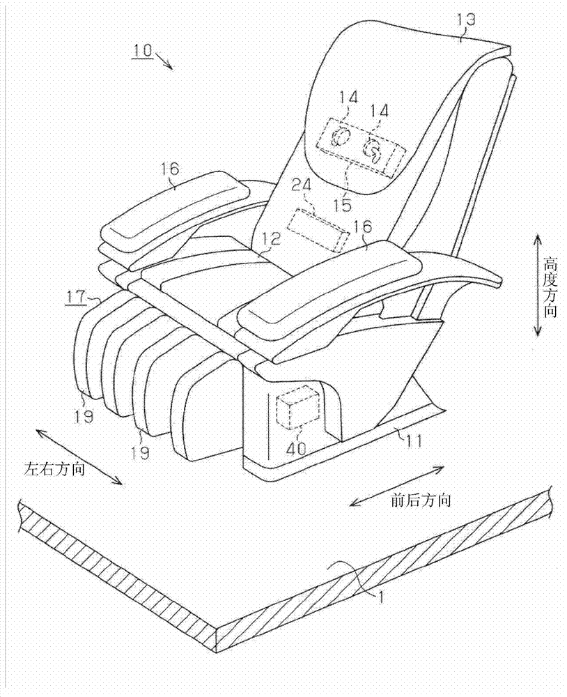
[0036] refer to figure 1 , the structure of the massage machine 10 as a swing device will be described.

[0037] The massage machine 10 includes a support portion 11 placed on the floor 1 , a seat portion 12 , a backrest portion 13 , a control portion 24 , and a swing portion 40 . The backrest 13 is capable of tilting movement. The seat portion 12 is used to support the user's buttocks. The backrest 13 includes an effect member 14 and a massage mechanism 15 . The massaging mechanism 15 is used to act on the back of the user by driving the acting element 14 in response to a control signal from the control unit 24 . The massage machine 10 has armrests 16 on the left and right sides of the seat 12 . Massage machine 10 has footrest 17 on the front side of seat portion 12 . When the user sits on the massage machine 10 , the lower legs of the user's legs are placed on the footrest 17 .

[0038] Hereinafter, the vertical direction is defined as the height direction. Furthermor...

no. 2 Embodiment approach

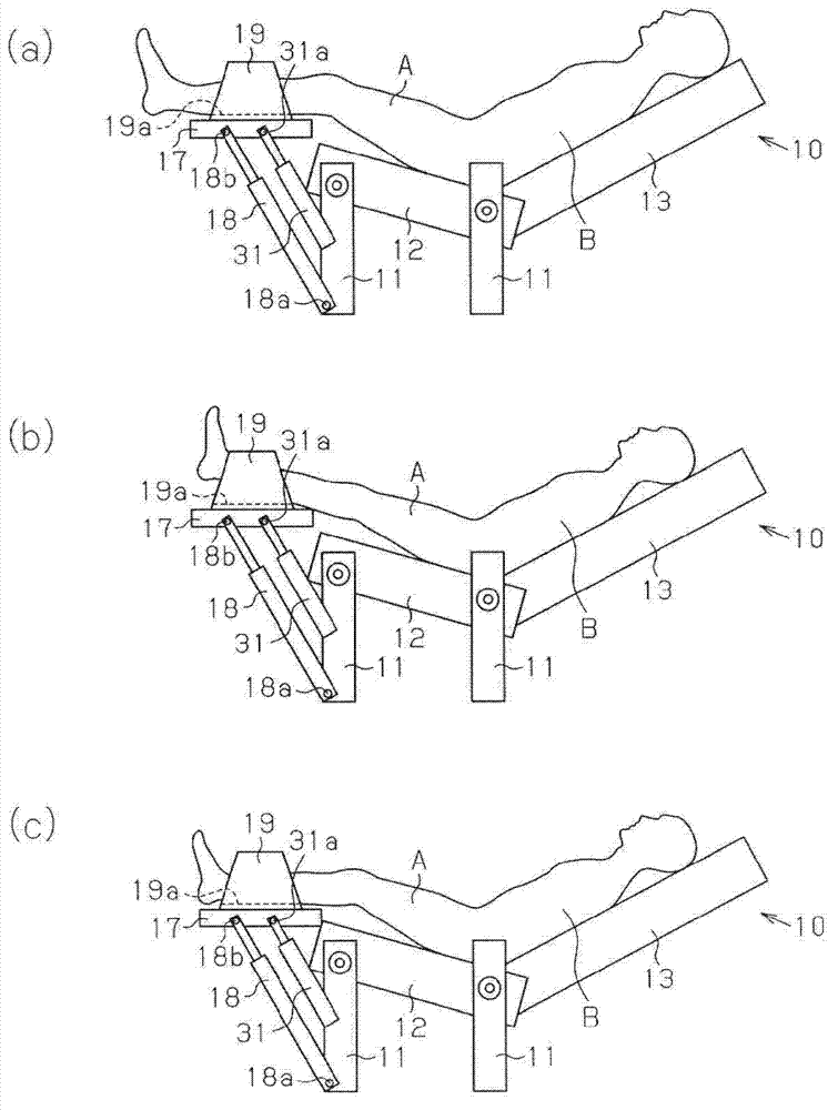
[0054] refer to image 3 , the massage machine 10 as the swing device of the second embodiment will be described.

[0055] Compared with the massage machine 10 of the first embodiment, the massage machine 10 of the second embodiment has a different structure in the following parts, but has the same structure in other parts. In addition, the same code|symbol is attached|subjected to the structure common to the massaging machine 10 of 1st Embodiment, and a part or all of the description is abbreviate|omitted.

[0056] The massage machine 10 according to the first embodiment includes a first electric motor mounted on the support rotation shaft 18a and the first footstool rotation shaft 18b so as to be movable relative to the support rotation shaft 18a and the first footstool rotation shaft 18b. The telescopic mechanism 18 and the 2nd electric telescopic mechanism 31 attached to the 1st footstool rotation shaft 31a so that they can move freely with respect to the 1st footstool ro...

no. 3 Embodiment approach

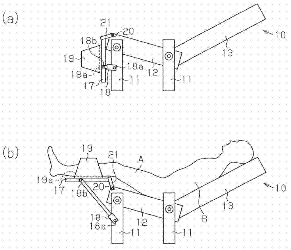
[0063] refer to Figure 4 , the massage machine 10 as the swing device of the third embodiment will be described.

[0064] Compared with the massage machine 10 of the second embodiment, the massage machine 10 of the third embodiment has a different structure in the following parts, but has the same structure in other parts. In addition, the same code|symbol is attached|subjected to the structure common to the massaging machine 10 of 2nd Embodiment, and a part or all of the description is abbreviate|omitted.

[0065] The massage machine 10 according to the second embodiment includes a connection member 21 whose one end (base end) is attached to the seat rotation shaft 20 and whose other end is connected to the footrest 17 . On the other hand, the massage machine 10 according to the third embodiment includes a connection member 21 whose one end (base end) is attached to the seat rotation shaft 20 and whose other end (tip end) is attached to the third footrest rotation shaft 22 ...


PUM


Abstract

The invention provides a swing device which can enable a body to relax by swinging legs of a user. The swing device (10) comprises a seat part (12) which is used for supporting a buttock of a user, a leg supporting part (19) which is used for supporting a support face (19a) of the leg, a swing part (40) which is used for enabling the support part to swing from left to right along the seat part. The leg supporting part (19) comprises a position adjusting mechanism (18, 31) which is used for changing the position of the support face with respect to the seat part. The position adjusting mechanism (18, 31) changes the position of the support face when the leg supporting part conducts swing movement, and thereby the support face is in a rising state, higher than the seat part. The support face (19a) is in a non-uphill state.

Description

technical field [0001] The present invention relates to an oscillating device for relaxing the body. Background technique [0002] Conventionally, a chair-type massage machine is known as a swing device capable of performing a body-relaxing massage operation on a user in a seated state (for example, refer to Patent Document 1). The chair-type massage machine of this Patent Document 1 includes a footstool on which a user's legs can be placed, and a foot support member capable of swinging left and right for supporting both ankles of a user is provided on the footstool. Then, along with the reciprocating movement of the foot supporting member in the left and right direction, both legs of the user swing around the waist of the user, so that the tense state of the legs of the user can be relieved. [0003] Patent Document 1: Japanese Patent Application Laid-Open No. 10-328262 [0004] However, in the above-mentioned chair-type massage machine as a swinging device, the foot rece...

Claims


Application Information

Patent Timeline
Patent Type & Authority Applications(China)
IPC IPC(8): A61H1/00A61H23/04
Inventor 白泽直人森川大辅筒井慎治佐藤亮太中野纪夫
Owner PANASONIC CORP
Why Eureka
Try Eureka