
Ceramic riveting die with conducting core

A technology of riveting punching and ceramic materials, applied in the direction of gear transmission mechanism, clutch, mechanical drive clutch, etc., can solve the problems of wrong riveting structure and wrong information, and achieve the effect of improving the sensing accuracy and reducing the cost

Active Publication Date: 2013-06-19
SCHAEFFLER TECH AG & CO KG
View PDF6 Cites 0 Cited by
  • Summary
  • Abstract
  • Description
  • Claims
  • Application Information

AI Technical Summary

Problems solved by technology

This leads to an undesired situation, i.e. technically not defective, just riveted components such as double clutches are disassembled again due to wrong information and only because the rivet monitoring device shows a wrong riveting configuration

Method used


Image

  • Ceramic riveting die with conducting core
  • Ceramic riveting die with conducting core
  • Ceramic riveting die with conducting core

Examples


Embodiment Construction

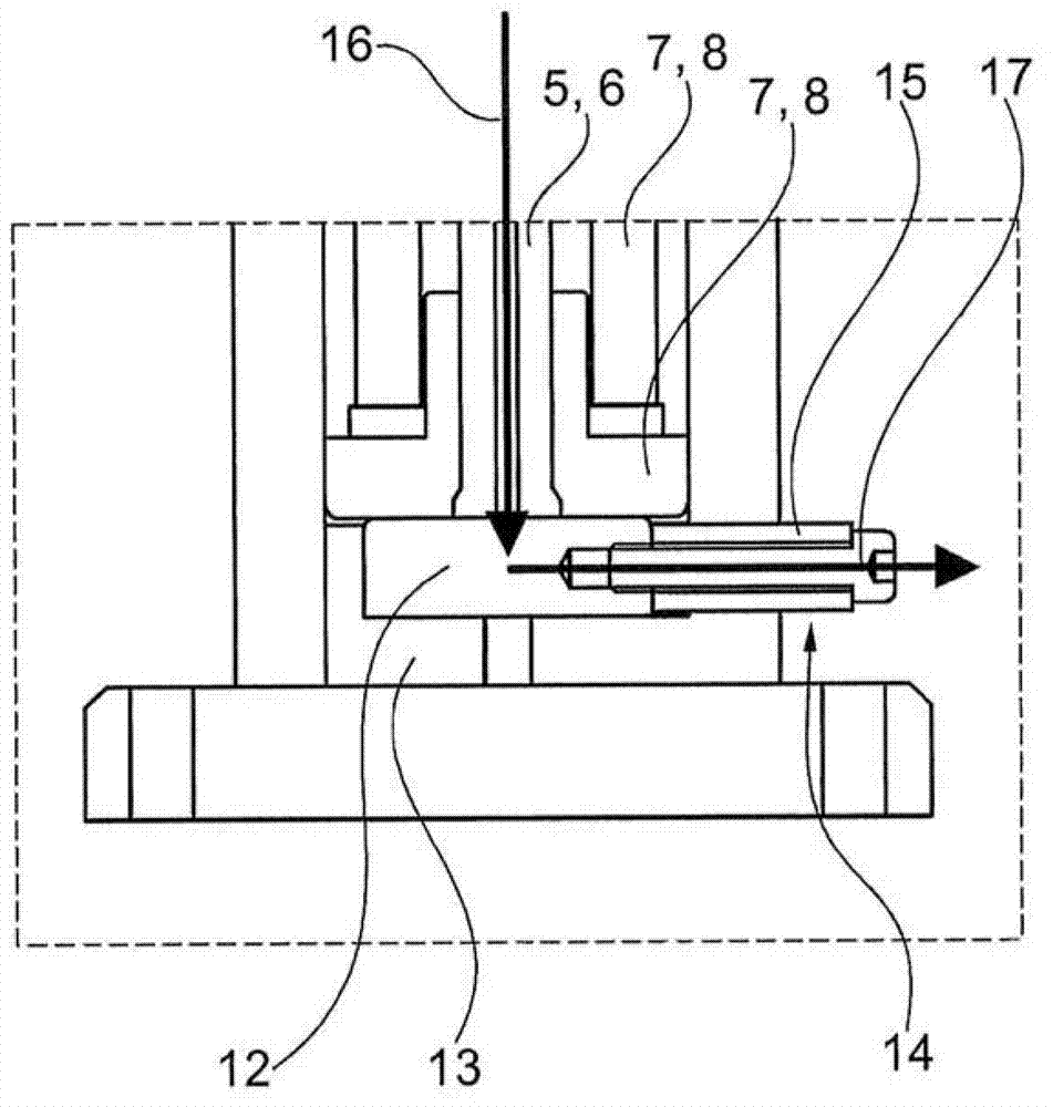
[0036] The drawings are only schematic and are used only for the understanding of the invention. Identical elements are provided with the same reference numerals.

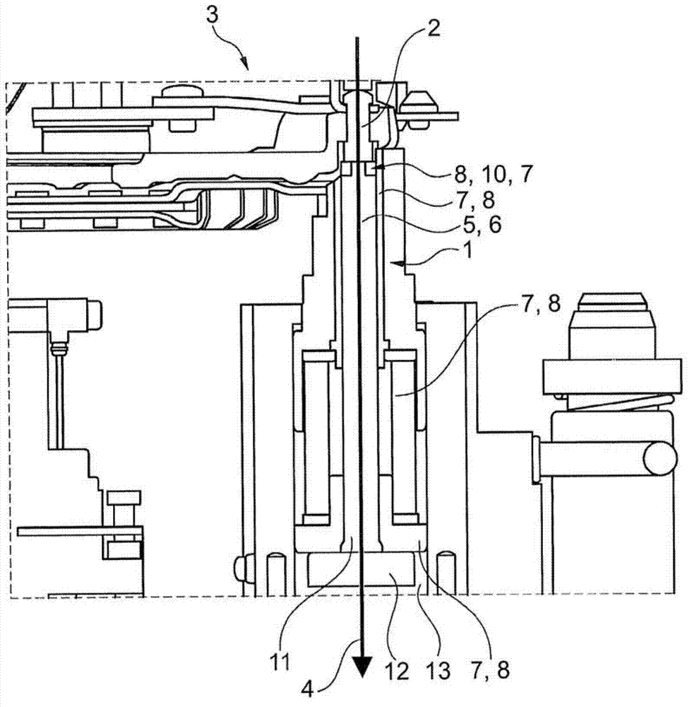
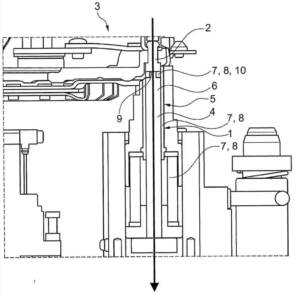
[0037] figure 1 A first embodiment of a riveting punch 1 according to the invention is shown for riveting a rivet 2 to a clutch, such as a double clutch 3 . However, the riveting die 1 can also be used when riveting lever actuators or dual mass flywheels.

[0038] The riveting die 1 is elongated and extends along a longitudinal axis 4 . Its body 5 has an electrically conductive core 6 surrounded by an electrically insulating cover layer 7 . The electrically insulating cover layer 7 acts as an insulation. It is divided into a plurality of insulating sections 8 .

[0039] An insulating end piece 10 is provided on the end 9 of the riveting die 1 adjacent to the rivet. The insulating end piece 10 is annular and made of ceramic. The core 6 of the riveting die 1 is also made of ceramics. Of course, the insulating...


PUM


Abstract

A riveting die for riveting rivets onto a clutch, such as a double clutch, a lever actuator, or a dual mass flywheel has a body extending along the longitudinal axis. The body has a conducting core, which is attached to the rivets and transmits current from the rivets to a sensor, wherein the core is at least partially enclosed by pressure-resistant insulating covering layer. The invention further relates to a method for riveting rivets onto a clutch, such as a double clutch, a lever actuator, or a dual mass flywheel, wherein the riveting die tightly attached to the rivets.

Description

technical field [0001] The invention relates to a riveting die for riveting a rivet to a clutch, such as a double clutch or to a lever actuator or to a dual mass flywheel, said riveting die having a body extending along a longitudinal axis, said body having a An electrically conductive wick, wherein the wick is designed to be in close contact with the rivet and is designed to conduct current from the rivet to the sensor. Background technique [0002] Riveting dies are known for placing on a rivet and introducing forces into the rivet, causing deformation of the rivet. Rivets are used here to connect two components to each other. [0003] Generally, such riveting dies are also used when riveting clutches, such as friction clutches, double clutches and lever actuators. For example, DE 32 24 404 C2 already discloses a friction clutch and its assembly method. The friction clutch disclosed in this document has a pressure plate which can be loaded by at least one energy accumul...

Claims


Application Information

Patent Timeline
IPC IPC(8): B21J15/38
CPCB21J15/14B21J15/28B21J15/36F16D21/06F16D2250/00
Inventor T·米歇尔巴赫D·施特拉斯布格尔
Owner SCHAEFFLER TECH AG & CO KG
Learn More