Automobile air conditioning system

A technology for automotive air conditioning systems and cabins, applied in vehicle components, air handling equipment, heating/cooling equipment, etc., can solve problems such as increasing vehicle load, discounting in-vehicle comfort, and affecting the driver's line of sight, avoiding high and low temperature shocks , to meet the comfort requirements, to ensure the effect of temperature and humidity

Active Publication Date: 2013-06-19
HANGZHOU SANHUA RES INST CO LTD
View PDF6 Cites 3 Cited by
  • Summary
  • Abstract
  • Description
  • Claims
  • Application Information

AI Technical Summary

Problems solved by technology

[0004] However, in the various heating methods mentioned above, if an independent heat source is used, such as purely using PTC for heating, it will consume more battery energy, which will reduce the mileage of the car; if fuel heating is used, not only the heating efficiency is low, It will also pollute the environment and increase the load on the car
In addition, in winter, when the dew point temperature near the inner glass of the car is higher than the temperature of the outer glass, fog will be generated, which will affect the driver's sight. Cold wind, which can cause discomfort in the cabin when the weather is relatively cold
And when the temperature outside the car is below zero, there may be rainwater or snow accumulated on the surface of the heat exchanger outside the car, causing the energy efficiency ratio to decrease during heating operation, so deicing or defrosting is required to improve heat transfer efficiency
However, in the existing car air conditioner, the compartment is not ventilated during deicing, which will cause the temperature in the compartment to drop, which will greatly reduce the comfort in the car.

Method used


Image

  • Automobile air conditioning system
  • Automobile air conditioning system
  • Automobile air conditioning system

Examples


specific Embodiment approach

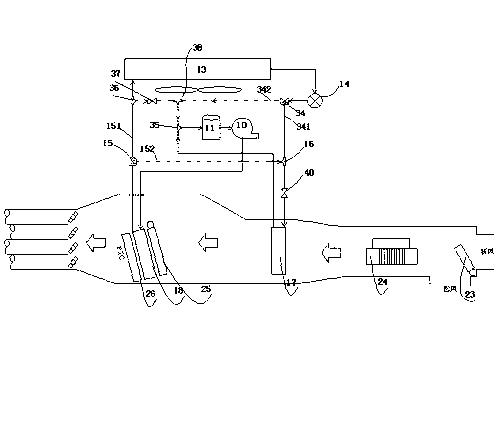
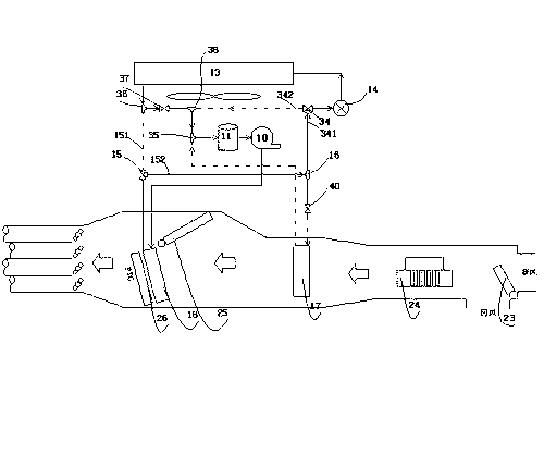
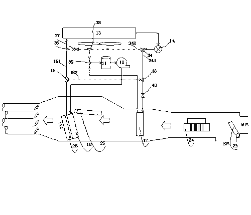
[0070] Introduce the second specific embodiment of the present invention below, Figure 7 It is a schematic diagram of the pipeline connection of the second specific embodiment of the present invention. This embodiment is an improvement on the above first specific embodiment. A bypass channel is provided for the heat exchanger 13 outside the compartment, specifically a three-way is provided at the inlet and outlet of the heat exchanger 13 outside the compartment. Pipe fittings, the third electromagnetic three-way control valve, such as Figure 7 In the middle, a third electromagnetic three-way control valve 28 is arranged in the pipeline between the heat exchanger 13 outside the vehicle compartment and the second electromagnetic three-way control valve 15, and is arranged in the pipeline after the outlet of the heat exchanger 13 outside the vehicle compartment A three-way pipeline piece 27, an interface of the third electromagnetic three-way control valve 28 is connected with...

Embodiment approach

[0072] The other three operating modes can refer to the first specific implementation mode above, and the relevant valves controlled by the electromagnetic control can be operated to switch the relevant flow direction, and the flow mode of the refrigerant can be changed, which will not be described here.


PUM


Abstract

An automobile air conditioning system comprises a compressor, a steam-liquid separator located in front of an air inlet of the compressor, a heater, a cooler, a heat exchanger located outside an automobile compartment, and a throttling component. The heater and the cooler are used for heating, or cooling or defogging for the automobile compartment according to work conditions in the automobile compartment. The heater is connected with an air exhaust of the compressor, and high-temperature high-pressure refrigerants pass through the inside of the heater to provide heat selectively for the inside of the automobile compartment. In a dehumidification mode, low-temperature low-pressure refrigerants pass through the cooler, wind sent to the inside of the automobile compartment firstly passes through the cooler for dehumidification and then passes through the heater, and then the wind is sent to the inside of the automobile compartment. The heater can be used for heating or not heating the dehumidified wind selectively according to the work conditions in the automobile compartment, and comfortableness in the automobile compartment is guaranteed.

Description

technical field [0001] The invention relates to the technical field of automobile air conditioning, in particular to an electric automobile air conditioning system. Background technique [0002] With the development of low-carbon economy, more stringent requirements are put forward for energy saving and emission reduction. Electric vehicles will become one of the aspects of future automobile development due to their energy-saving and environmental protection features. However, since electric vehicles use batteries as a power source, their air-conditioning systems are also different from the original automotive air-conditioning systems. [0003] Traditional internal combustion engine vehicles can use the waste heat of the internal combustion engine and the heat of the engine exhaust to heat the cabin, while the power of electric vehicles mainly comes from the motor, which lacks the heat of the engine to be used, making it difficult to meet the heating requirements in winter. ...

Claims


Application Information

Patent Timeline
Patent Type & Authority Applications(China)
IPC IPC(8): B60H1/00
Inventor 黄宁杰刘维华李雄林
Owner HANGZHOU SANHUA RES INST CO LTD
Why Eureka
Try Eureka