
Prefabricated concrete structure architecture electric pre-buried laying method

A concrete structure and building electrical technology, which is applied in the direction of buildings, building components, building structures, etc., can solve the problem that the cast-in-place layer of the pipeline cannot cover the intersection of the pipeline, the accurate positioning of the junction box and the box, and the construction quality of the cast-in-place layer. problems such as hidden dangers, to achieve the effect of reducing labor input, improving construction efficiency, and optimizing design

Active Publication Date: 2013-06-19
CHINA 22MCC GROUP CORP
View PDF4 Cites 8 Cited by
  • Summary
  • Abstract
  • Description
  • Claims
  • Application Information

AI Technical Summary

Problems solved by technology

At present, the pre-embedding method of strong and weak wire pipes in the prefabricated concrete structure roof is basically placed in the cast-in-place layer. In this way, due to the large number of pipelines, the cast-in-place layer with only half the thickness of the roof cannot cover the crossing position of the pipelines. It brings great difficulties to the construction. In addition, because the strong and weak wires and pipes are all concentrated in the cast-in-place layer, it brings great hidden dangers to the construction quality of the cast-in-place layer; the interference of strong electricity on communication signals is also very serious
However, the pre-embedding of the boxes, wire boxes and wire pipes in the prefabricated wall is mostly a rough operation method, and the precise positioning of the wire box and the box body cannot be performed, which will bring a lot of inconvenience to the future installation.

Method used


Image

  • Prefabricated concrete structure architecture electric pre-buried laying method
  • Prefabricated concrete structure architecture electric pre-buried laying method

Examples


Embodiment Construction

[0020] The present invention is described in detail below with reference to accompanying drawing and embodiment:

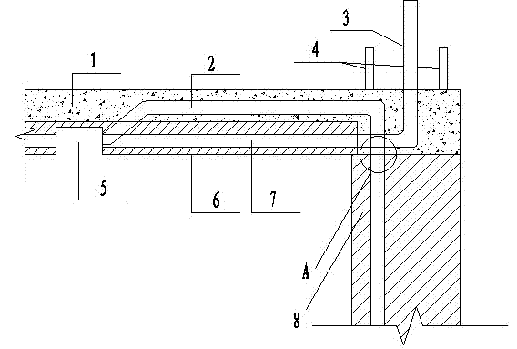
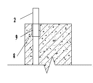
[0021] attached figure 1 , 2 It can be seen that a prefabricated concrete structure building electrical pre-embedded layout method includes the construction of the prefabricated slab 6, the construction of the prefabricated wall 8 and the construction of the roof cast-in-place layer 1, and the prefabricated slab 6 is provided with weak current communication line pipes and sockets Pipeline circuit and air-conditioning socket pipeline circuit 7; the roof cast-in-place layer 1 is provided with a lighting circuit pipe and a main line pipe 2; the prefabricated board 6 is prefabricated with a light box 5 for electric lamps, and the line pipe is reserved in the light box 5 Throw out the surface layer of the prefabricated board 6 and connect it with the lighting circuit in the cast-in-place layer 1; the joints of the prefabricated board 6 are provided with a wire pipe in...


PUM


Abstract

The invention relates to a prefabricated concrete structure architecture electric pre-buried laying method which comprises construction of a prefabricated slab, construction of a prefabricated wall, and construction of a top plate cast-in-place layer, wherein a weak current communication line tube, a socket pipe line return circuit and an air conditioning socket pipe line return circuit are arranged inside the prefabricated plate; and a lighting return circuit line pipe and a main line pipe are arranged in the top plate cast-in-place layer. According to the prefabricated concrete structure architecture electric pre-buried laying method, the number of line pipes laid in the cast-in-place layer is reduced; according to the method, through regulation of procedures, reasonable arrangement is carried out on strong and weak line pipes, the arrangement of pre-buried line pipes is guided into the industrialization field, construction efficiency is improved, manual investment is reduced, and construction quality is improved; and optimization design is also carried out on node connection of a prefabricated part and a cast-in-place part, cost is reduced, and production efficiency is improved.

Description

technical field [0001] The invention relates to a building construction method, in particular to an electrical pre-embedded layout method for a prefabricated concrete structure building. Background technique [0002] In the construction process of prefabricated concrete structures, it is necessary to produce some other components such as walls, roofs and stairs in the factory, and then transport them to the construction site for assembly operations, especially to divide the overall roof into two parts and make half of them prefabricated. slab, and the other half is cast-in-place. At present, the pre-embedding method of strong and weak wire pipes in the prefabricated concrete structure roof is basically placed in the cast-in-place layer. In this way, due to the large number of pipelines, the cast-in-place layer with only half the thickness of the roof cannot cover the crossing position of the pipelines. It brings great difficulties to the construction. In addition, because t...

Claims


Application Information

Patent Timeline
IPC IPC(8): E04C2/52
Inventor 霍晓光刘通王慎栋
Owner CHINA 22MCC GROUP CORP
Learn More