Circulating fan and fan blade group thereof

A circulating fan and fan blade technology, applied in the field of circulating fans, can solve the problems of inability to save energy, increase space configuration, and increase power consumption, reduce volume and power consumption, simplify space configuration, and reduce power loss. Effect

Active Publication Date: 2013-06-19
DELTA ELECTRONICS INC
View PDF10 Cites 2 Cited by
  • Summary
  • Abstract
  • Description
  • Claims
  • Application Information

AI Technical Summary

Benefits of technology

This patented technology uses complex powers for driving an electric blower or other device with fewer parts than traditional designs while still being able to efficiently cool down indoor spaces without consuming too much electrical current from batteries. It also reduces size and weight compared to older devices but at lower costs. Overall, this innovative design helps save money on fuel usage and improve environmental performance.

Problems solved by technology

This patented technical problem addressed in this patents relates to improving cooling efficiency while minimizing noise emissions during winter months without adding excessive weight or size beyond what would otherwise make up room available.

Method used


Image

  • Circulating fan and fan blade group thereof
  • Circulating fan and fan blade group thereof
  • Circulating fan and fan blade group thereof

Examples


Embodiment Construction

[0034] Some typical embodiments embodying the features and advantages of the present invention will be described in detail in the following description. It should be understood that the present invention can have various changes in different aspects, all of which do not depart from the scope of the present invention, and the description and drawings therein are essentially for illustrative purposes, rather than limiting the present invention .

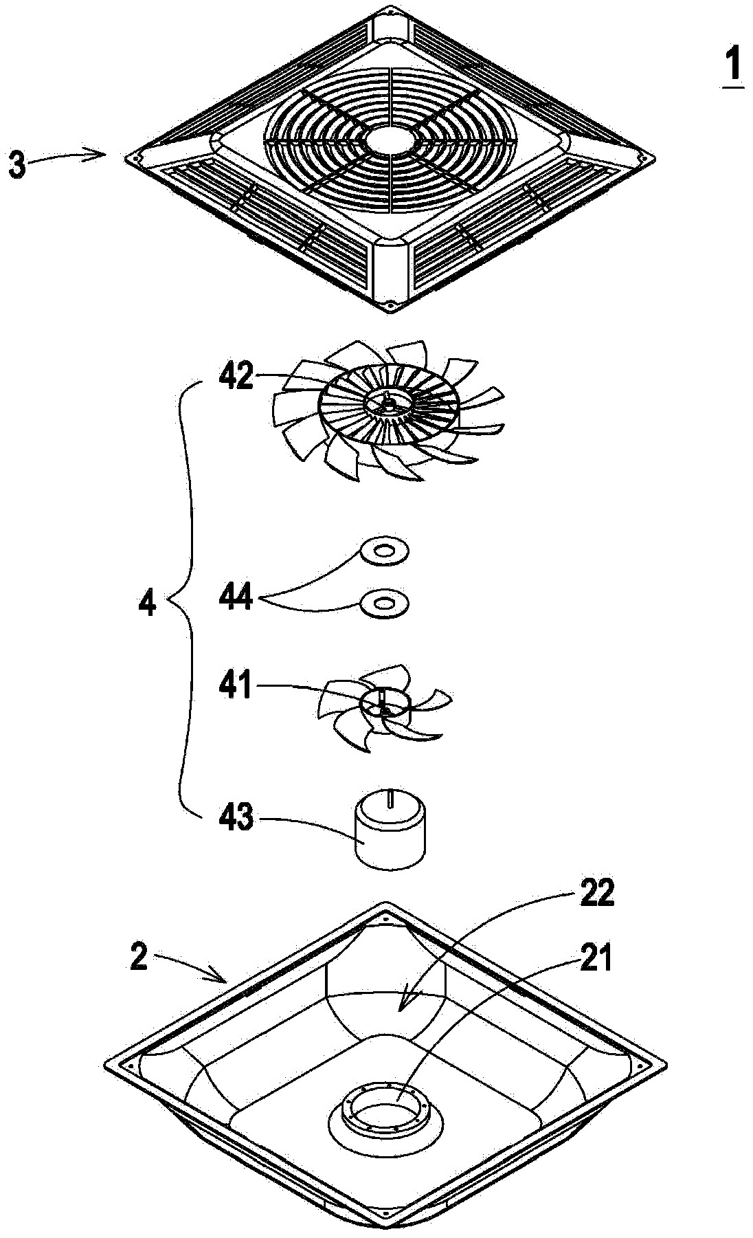
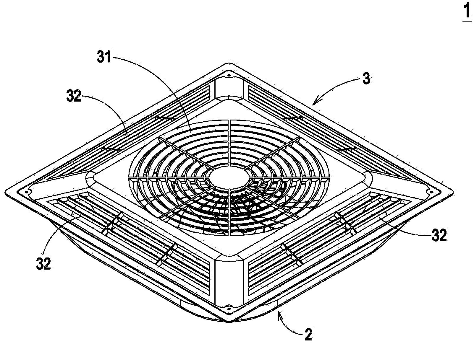
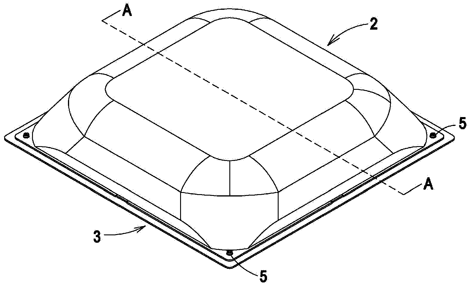
[0035] See figure 1 , Which is a schematic structural diagram of a circulating fan according to a preferred embodiment of the present invention. Such as figure 1 As shown, the circulation fan 1 of the present invention can mainly improve convection circulation and control the ambient temperature, and the circulation fan 1 at least includes a casing 2, a cover 3 and a fan blade group 4. Wherein, the housing 2 has a base 21, and the base 21 substantially has a cylindrical, cubic or cuboid space. It can be formed integrally with the housing...


PUM


Abstract

The invention provides a circulating fan and a fan blade group of the circulating fan. The circulating fan at least comprises a shell body, a cover body, and a fan blade group. The shell body comprises a base seat, and the cover body and the shell body are jointed to form containing space. The fan blade group is arranged in the containing space. The fan blade group at least comprises a first impeller, a second impeller, a motor, and a plurality of magnetic components. The second impeller is arranged near the first impeller. The motor is fixedly arranged on the base seat of the shell body and connected with the first impeller to drive the first impeller to run. The magnetic components are arranged between the first impeller and the second impeller. With wind power generated by running of the first impeller and magnetic torque generated by magnetic eddy currents between the magnetic components, the second impeller is driven to run under non-contact force. According to the circulating fan and the fan blade group of the circulating fan, impellers with smaller fan blades are chosen to be used for being matched with the motor with smaller size, and thus effects that the size and power consumption are reduced, space configuration is simplified, and cost is reduced are achieved.

Description


Claims


Application Information

Patent Timeline
Owner DELTA ELECTRONICS INC
Why Eureka
Try Eureka