Super-resolution fluorescent lifetime imaging method and device based on stimulated emission lost

A technology of stimulated emission loss and super-resolution fluorescence, which is applied in material excitation analysis, measurement devices, fluorescence/phosphorescence, etc., can solve problems that are difficult to meet the needs of scientific research, and achieve fluorescence lifetime imaging and long-distance fluorescence lifetime imaging , The effect of breaking the limitation of the optical diffraction limit

Inactive Publication Date: 2014-12-17
ZHEJIANG UNIV
View PDF7 Cites 0 Cited by
  • Summary
  • Abstract
  • Description
  • Claims
  • Application Information

AI Technical Summary

Problems solved by technology

[0004] However, limited by the optical diffraction limit, the spatial resolution of the traditional fluorescence lifetime imaging method is only about 200 nm, which is difficult to meet the needs of scientific research

Method used


Image

  • Super-resolution fluorescent lifetime imaging method and device based on stimulated emission lost
  • Super-resolution fluorescent lifetime imaging method and device based on stimulated emission lost
  • Super-resolution fluorescent lifetime imaging method and device based on stimulated emission lost

Examples


Embodiment Construction

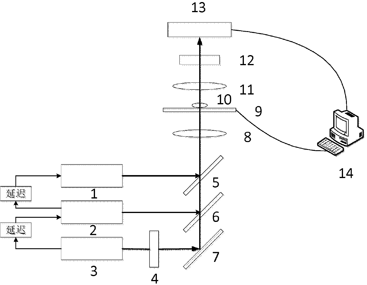
[0038] Such as figure 1 As shown, a super-resolution fluorescence lifetime imaging device based on stimulated emission loss, including: a first laser 1, a second laser 2, a third laser 3, an electro-optic modulator 4, a first dichroic mirror 5, a second dichroic mirror 6. A third dichroic mirror 7, a first objective lens 8, a nano-translation stage 9, a sample 10, a second objective lens 11, a filter 12, a photomultiplier tube 13, and a computer 14.

[0039] The light source used in the present invention is a laser, therefore, the first light source, the second light source and the third light source correspond to the first laser 1 , the second laser 2 and the third laser 3 respectively.

[0040] The first laser 1, the second laser 2 and the third laser 3 are controlled by the computer 14, so that the first laser 1, the second laser 2 and the third laser 3 are turned on with a certain time difference, so that the first laser beam, the STED light and the second laser beam When...


PUM


Abstract

The invention discloses a super-resolution fluorescent lifetime imaging method based on stimulated emission lost. The super-resolution fluorescent lifetime imaging method based on the stimulated emission lost includes the flowing steps: (1) projecting a first laser beam on a to-be-tested sample and activating grains in the to-be-tested sample to an excited sate; (2) utilizing stimulated emission depletion (STED) light to consume the number of the grains which are in the excited state in step (1); (3) utilizing a second laser beam to stimulate the rest grains to emit fluorescent light and collecting the fluorescent light to obtain corresponding fluorescence intensity images; (4) arranging delay between the second laser beam and the STED light, changing delay time, repeating step (3), and obtaining the fluorescence intensity images under different delay time; (5) conducting treatment on the fluorescence intensity images in different delay time through a computer, and fitting a spot intensity attenuation law, inverting lifetime images, and completing scanning of one point of the to-be-tested sample; (6) and completing two-dimension scanning on the sample to be tested by changing the positions where the beam is projected on the to-be-tested sample. The invention further discloses a device used for implementing the method.

Description

technical field [0001] The invention belongs to the field of fluorescence lifetime imaging, in particular to a method and device for long-distance detection of fluorescence lifetime imaging under super-resolution based on stimulated emission loss. Background technique [0002] Fluorescence is what happens when a molecule absorbs energy and its ground state electrons are excited to an excited state and then return from the excited state to the ground state. The fluorescence lifetime refers to the average stay time of the molecule in the excited state before returning to the ground state after being excited by the light pulse. The fluorescence lifetime of the fluorescent substance is generally absolute and is not affected by factors such as the intensity of the excitation light, the intensity of the fluorophore, and photobleaching. It is only related to the structure of the cell itself and its microenvironment. Therefore, fluorescence lifetime imaging microscopy (FLIM), which...

Claims


Application Information

Patent Timeline
Patent Type & Authority Patents(China)
IPC IPC(8): G01N21/64
CPCG01N21/6458G01N21/6408G02B21/16
Inventor 葛剑虹蔡欢庆匡翠方刘旭王毅
Owner ZHEJIANG UNIV
Why Eureka
Try Eureka