
A device for compensating knife edge-driving reaction force in a lighting scanning direction and a lithographic apparatus

A driving device, lighting scanning technology, applied in the field of integrated circuit manufacturing equipment, can solve problems such as motion reaction force, and achieve the effect of reducing the impact

Active Publication Date: 2013-06-19
SHANGHAI MICRO ELECTRONICS EQUIP (GRP) CO LTD
View PDF8 Cites 7 Cited by
  • Summary
  • Abstract
  • Description
  • Claims
  • Application Information

AI Technical Summary

Problems solved by technology

[0007] The purpose of the present invention is to overcome the technical defects existing in the prior art, and provide a device and lithography equipment for compensating the driving reaction force of the illumination scanning to the knife edge, so as to solve the technology for the movement reaction force of the illumination scanning to the knife edge driving motor question

Method used


Image

  • A device for compensating knife edge-driving reaction force in a lighting scanning direction and a lithographic apparatus
  • A device for compensating knife edge-driving reaction force in a lighting scanning direction and a lithographic apparatus
  • A device for compensating knife edge-driving reaction force in a lighting scanning direction and a lithographic apparatus

Examples


Embodiment Construction

[0018] Specific embodiments of the present invention will be described in detail below in conjunction with the accompanying drawings.

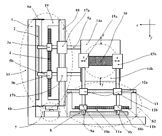
[0019] The invention discloses a device for compensating the driving reaction force of the lighting scanning to the knife edge, comprising: a knife edge driving device in the X direction and a Y direction; a first compensation unit for eliminating the reaction force in the X direction; a device for eliminating the reaction force in the Y direction The second compensation unit; the support unit, including mutually perpendicular X-direction brackets and Y-direction brackets; the first compensation unit is connected to the X-direction bracket; the second compensation unit is connected to the Y-direction bracket through at least one flexible member, and It is connected with the X-direction support through a damping unit.

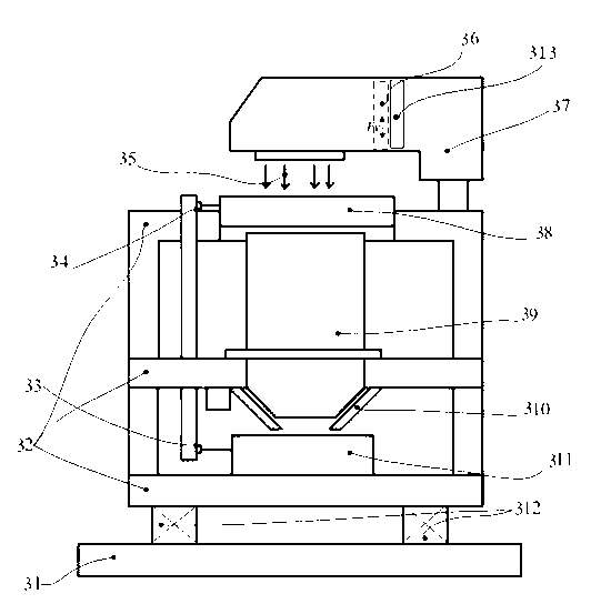
[0020] Such as figure 1 as shown, figure 1 It is a structural schematic diagram of the lithography equipment involved in the...


PUM


Abstract

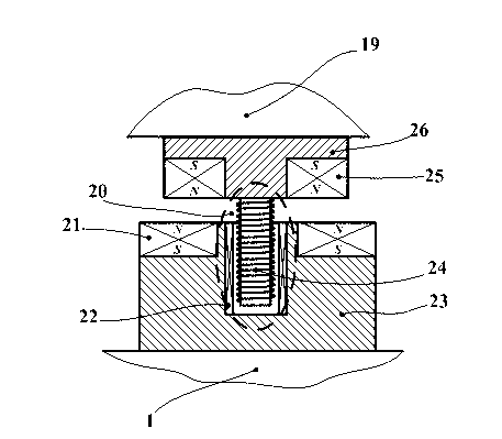
The invention discloses a device for compensating knife edge-driving reaction force in a lighting scanning direction, and the device comprises: a main bracket (1), a Y-direction bracket (19), a Y-direction knife edge drive device (b1), an X-direction bracket (11a), and an X-direction edge direction drive device (b2), wherein the X-direction drive device is arranged on the X-direction bracket, the X-direction bracket is arranged on the main bracket, and the Y-direction knife edge drive device is arranged on the Y-direction bracket; and the device of the invention further comprises a compensation unit and support springs, wherein the bottom part of the Y-direction bracket is arranged on the main bracket through the compensation unit, and the side wall of the Y-direction bracket is connected with the main bracket through the support springs.

Description

technical field [0001] The invention relates to the technical field of integrated circuit manufacturing equipment, in particular to a device and photolithography equipment for compensating the driving reaction force of illumination scanning to the knife edge. Background technique [0002] Lithography equipment is a kind of equipment used in the manufacture of integrated circuits. The use of this equipment includes but is not limited to: integrated circuit manufacturing lithography equipment, liquid crystal panel lithography equipment, photomask marking equipment, MEMS (micro-electromechanical systems) / MOMS (micro-optical machine system) lithography equipment, advanced packaging lithography equipment, printed circuit board lithography equipment and printed circuit board processing equipment, etc. [0003] Photolithography refers to the complex process of sequentially transferring the chip patterns on a series of reticles to the corresponding layers of the silicon wafer thro...

Claims


Application Information

Patent Timeline
Patent Type & Authority Applications(China)
IPC IPC(8): G03F7/20
Inventor 王天明
Owner SHANGHAI MICRO ELECTRONICS EQUIP (GRP) CO LTD
Learn More