

Workpiece clamp
A fixture and workpiece technology, applied in the field of workpiece fixtures for online cutting, can solve the problems of relying on additional tooling, irregular workpieces, and difficulty in clamping multiple workpieces at the same time, and achieve the effect of ensuring clamping
- Summary
- Abstract
- Description
- Claims
- Application Information
AI Technical Summary
Problems solved by technology
Method used
Image

Examples
Embodiment Construction
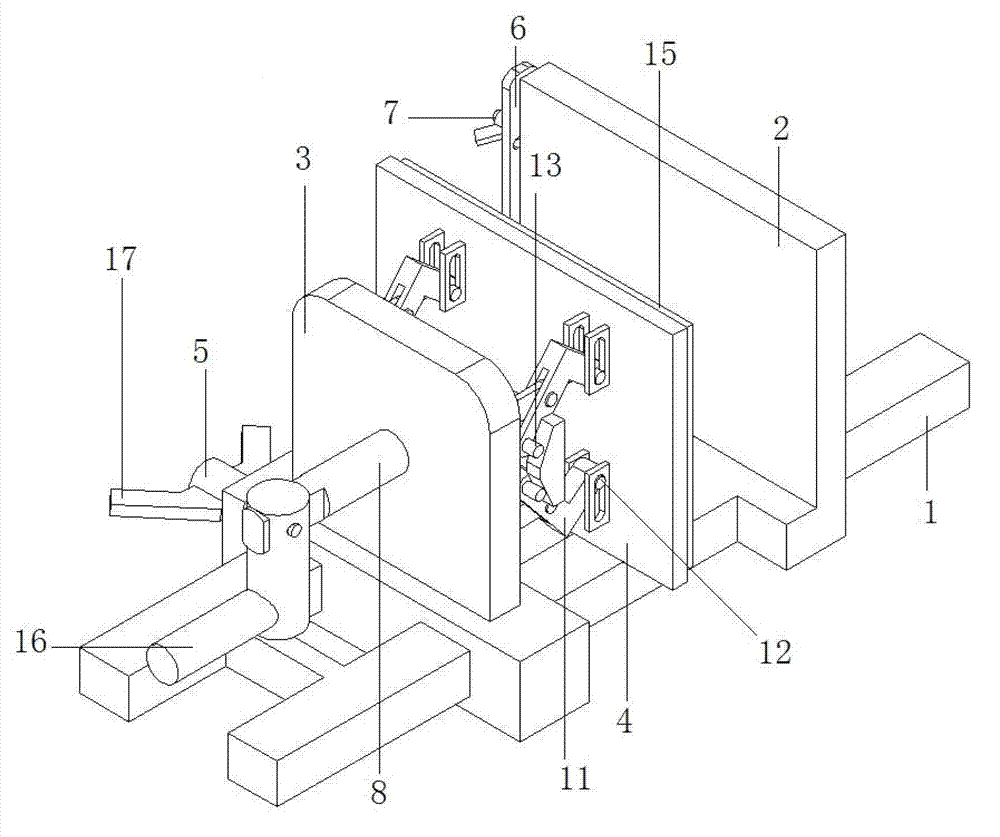
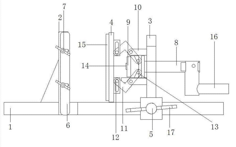
[0028] Below by embodiment, technical solution of the present invention is described further in conjunction with accompanying drawing:
[0029] Such as figure 1 , figure 2 A workpiece processing fixture shown includes a base 1, and the base 1 is provided with a reference seat plate 2 and a sliding clamping seat on a sliding clamping seat 3 opposite to the reference surface of the reference seat plate 2. Plate 4, the sliding clamping seat 3 is slidingly connected with the base 1, and the side of the sliding clamping seat 3 is provided with a positioning bolt 5, and the positioning bolt 5 is connected to the side of the base 1 in a tightened state. Closely attached, the side of the reference seat plate 2 is provided with a limit plate 6 that partially protrudes toward the direction of the sliding clamping seat 3, and the limit plate 6 is close to the surface of the reference seat plate 2 and the reference seat plate 2 The reference surface is vertical. The limiting plate 6 i...
PUM
 Abstract
Description
Claims
Application Information