
Knitting mechanism of flat knitting machine

A knitting needle and knitting technology, which is applied in knitting, textiles and papermaking, etc. It can solve the problem of ensuring the tightness of the connection between the knitting needle and the stitches, the inability to reduce the wear of the triangle between the knitting needles and the bottom plate, and the difficulty in lifting and separating the needles and stitches, etc. problems, to achieve the effect of reducing maintenance and repair costs, stabilizing the weaving process, and controlling flexibly and sensitively

Active Publication Date: 2014-11-05
TONGXIANG JUXING KNITTING MACHINERY MFGCO
View PDF8 Cites 0 Cited by
  • Summary
  • Abstract
  • Description
  • Claims
  • Application Information

AI Technical Summary

Problems solved by technology

[0002] The structural design of the knitting needles and stitches currently used in flat knitting machines is not reasonable enough, and it is difficult to effectively complete the lifting and separation of the knitting needles and stitches. When the knitting needles and stitches are lifted, it is also difficult to ensure the tight connection between the knitting needles and stitches sex
When the stitches are separated from the knitting needles, it is difficult for the knitting needles to be completely hidden in the needle grooves of the needle plate, which cannot reduce the wear of the knitting needles and the triangle of the bottom plate, and shorten the service life of the equipment
[0003] There are also relatively good knitting needles for flat knitting machines now, as disclosed on July 27, 2011, and the publication number is CN102134784A in the Chinese patent, which discloses a knitting needle for flat knitting machines. Hook, needle bar, needle butt and needle tail, the distance from the bottom edge of the needle bar to the upper edge of the needle butt is not greater than the height of the needle groove in the needle plate, and a slope is provided at the transition between the rear end surface and the bottom surface of the needle tail. When the knitting needles of the flat knitting machine do not need to participate in knitting, the butts of the needles will not be higher than the needle grooves, and will not follow the knitting needles to the loop forming position, thus not affecting the quality of the garment pieces. However, the connection between the knitting needles and the stitches The tightness of the knitting needles is poor, which reduces the accuracy of the knitting needles. In addition, although a bevel is provided at the transition between the rear end surface and the bottom surface of the needle tail, it is difficult to conveniently and effectively complete the lifting of the knitting needles and stitches. separate
[0004] To sum up, at present there is no simple structure, reasonable design, tight connection between knitting needles and stitches, which can effectively complete the lifting and separation of knitting needles and stitches, and when the stitches are separated from the knitting needles, the knitting needles The knitting mechanism of a flat knitting machine that can be completely hidden in the needle grooves of the needle plate

Method used


Image

  • Knitting mechanism of flat knitting machine
  • Knitting mechanism of flat knitting machine
  • Knitting mechanism of flat knitting machine

Examples


Embodiment Construction

[0035] The present invention will be further described in detail below in conjunction with the accompanying drawings and examples. The following examples are explanations of the present invention and the present invention is not limited to the following examples.

[0036] Example.

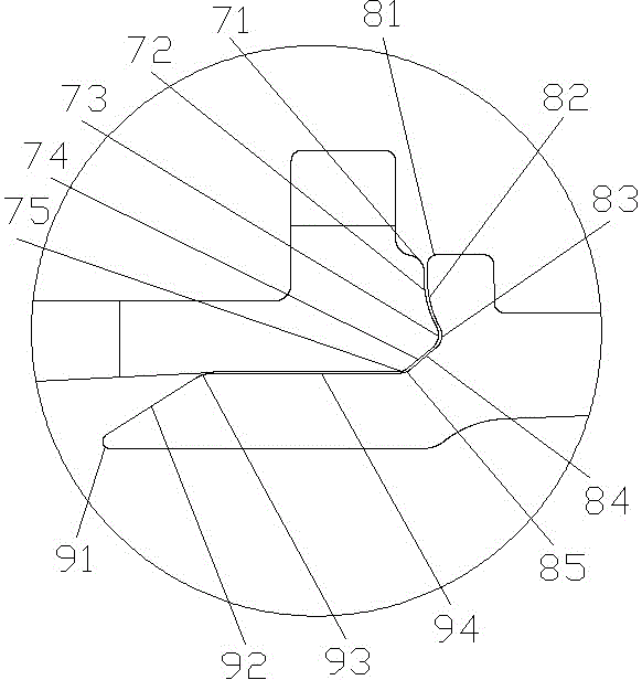
[0037] see Figure 1 to Figure 18 , the knitting mechanism of the flat knitting machine in this embodiment includes knitting needles and stitches, wherein the stitches are of an integrated structure.

[0038]The knitting needle in the present embodiment comprises needle latch 1, needle bar 2, needle body 3, knitting needle needle clock 6, knitting needle bump 7, shrapnel 10, needle latch rotating shaft 12 and needle hook 13, wherein, needle hook 13 is fixed At one end of the needle bar 2, one end of the needle body 3 is fixed on the other end of the needle bar 2, and the needle latch 1 is movably connected on the needle hook 13 through the needle latch rotating shaft 12, and the needle latch 1 can...


PUM


Abstract

The invention relates to a knitting mechanism of a flat knitting machine. At present, no knitting mechanism of the flat knitting machine can achieve the fact that a needle is tightly connected with a stitch, and support and separation of the needle and the stitch are effectively completed. The knitting mechanism comprises the needle and the stitch and is characterized in that the needle comprises a needle protrusion and an elastic piece, the elastic piece is fixed on the side face of the needle body, the needle protrusion is fixed at the other end of the needle body, and the needle protrusion successively comprises a needle upper round corner, a needle concave arc surface, a needle protruded arc surface, a needle inclined surface and a needle lower round corner from top to bottom. One end of the stitch is provided with a stitch groove and a stitch protrusion, the stitch groove successively comprises a stitch upper round corner, a stitch protrusion arc surface, a stitch concave arc surface, a stitch inclined surface and a stitch lower round corner form top to bottom, and the stitch protrusion successively comprises a lower arc surface, a guide inclined surface, an upper arc surface and a locating plane from bottom to top. According to the knitting mechanism of the flat knitting machine, the needle is tightly connected with the stitch, and the support and separation of the needle and the stitch can be effectively achieved.

Description

technical field [0001] The invention relates to a knitting mechanism of a flat knitting machine, which includes knitting needles and pins, and is specially used in computerized flat knitting machines. Background technique [0002] The structural design of the knitting needles and stitches currently used in flat knitting machines is not reasonable enough, and it is difficult to effectively complete the lifting and separation of the knitting needles and stitches. When the knitting needles and stitches are lifted, it is also difficult to ensure the tight connection between the knitting needles and stitches sex. When the stitches are separated from the knitting needles, the knitting needles are difficult to completely hide in the needle grooves of the needle plate, which cannot reduce the wear and tear of the knitting needles and the bottom plate triangle, shortening the service life of the equipment. [0003] There are also relatively good knitting needles for flat knitting ma...

Claims


Application Information

Patent Timeline
Patent Type & Authority Patents(China)
IPC IPC(8): D04B35/04
Inventor 李祥才
Owner TONGXIANG JUXING KNITTING MACHINERY MFGCO
Learn More