
Multifunctional hoisting support frame

A multi-functional, pole-tower technology, applied in the field of hoisting brackets, can solve the problems of complex and time-consuming installation of the new type of swallow-wing cross arm

Inactive Publication Date: 2013-06-26
STATE GRID CORP OF CHINA +1
View PDF4 Cites 4 Cited by
  • Summary
  • Abstract
  • Description
  • Claims
  • Application Information

AI Technical Summary

Problems solved by technology

[0003] In order to solve the problem that the power system faces the complex and time-consuming installation process of the new swallow-wing cross-arm, the following technical scheme is proposed

Method used


Image

  • Multifunctional hoisting support frame
  • Multifunctional hoisting support frame
  • Multifunctional hoisting support frame

Examples


Embodiment 1

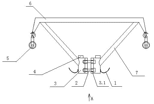
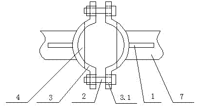
[0011] A multifunctional hoisting bracket installed on a power transmission line tower, which is composed of a horizontal beam 6 and two oblique rods 7 to form an approximately isosceles triangle frame, and the upper end of each oblique rod 7 is welded to the upper and lower ends of the horizontal beam 6 The hoop 3 is approximately semicircular, and the two ends of the hoop 3 are bent outwards to form an assembly part on which an assembly hole 3.1 is provided. Horizontal spacer plate 4 is installed above hoop 3. Hook 1 is installed on the outer surface of hoop 3, and fixed pulley 5 is installed respectively at the two ends of crossbeam 6. The height of hoop 3 is 200MM.

[0012] When the multifunctional hoisting bracket is installed on the tower, the limit plate 4 is just stuck on the top of the tower to ensure that the hoop 3 is always on the top of the tower.

[0013] When using the multi-functional hoisting bracket, an operator first climbs to the top of the tower, lifts t...

Embodiment 2

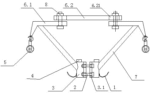
[0015] Since the beam in Embodiment 1 is a whole plate, when the space between the two hoops 3 does not completely coincide with the top of the tower, it will be very difficult to install the multifunctional hoisting bracket and tighten the first bolt 2. Can't even install. Therefore, Example 2 is proposed. It differs from Embodiment 1 in that the crossbeam 6 is changed into a telescopic structure, that is, the crossbeam 6 is composed of a middle crossbeam 6.2 and two side crossbeams 6.1. There are two rectangular holes 6.21 on the middle beam 6.2, and a through hole on the side beam 6.1. The middle beam 6.2 overlaps with the two side beams 6.1, and the second bolt 8 passes through the rectangular holes 6.21 and the two side beams 6.2. The through holes on the side beams 6.1 connect the middle beam 6.2 and the side beams 6.1 into one body. Between middle crossbeam 6.2 and two side crossbeams 6.1, can move relatively along rectangular hole 6.21, the length of promptly crossbe...


PUM

PropertyMeasurementUnit
Heightaaaaaaaaaa

Abstract

Disclosed is a multifunctional hoisting support frame which is installed on an electric transmission line pole tower. The multifunctional hoisting support frame is characterized by being a skeleton frame which is composed of a horizontal cross beam and two inclined rods and is in an approximate isosceles triangle shape. Upper ends of the inclined rods are fixed on tension sleeves which are installed at the upper end and the lower end of the horizontal cross beam, and the tension sleeves are in approximate semicircle shapes and are provided with assembling holes. Limiting plates are installed on the tension sleeves, hooks are installed on outer surfaces of the tension sleeves, and fixed pulleys are respectively installed at two ends of the cross beam. Due to the fact that the multifunctional hoisting support frame is installed at the top end of a pole tower and is kept away from working staff, operation space of the working staff is enlarged, and the multifunctional hoisting support frame is beneficial to hoisting heavy and long hardware fittings. According to the multifunctional hoisting support frame, the design with the pulleys on two sides is adopted, so that a hoisted object is enabled to bear force with two points, and labor intensity of the working staff is relieved. The multifunctional hoisting support frame is simple in structure, convenient to use, labor-saving, resource-saving and capable of improving working efficiency.

Description

technical field [0001] The invention belongs to the technical field of power distribution line construction, and in particular relates to a hoisting bracket used for installing fittings on power poles and towers and transmitting power materials. Background technique [0002] In 2007, Panjin Power Supply Company introduced Yan-wing cross-arms, synthetic insulators and other new power materials and equipment, and used them in large quantities in the equipment. Using the original equipment to install Yan-wing cross-arms was time-consuming and laborious. Contents of the invention [0003] In order to solve the problem that the power system is faced with the complex and time-consuming installation process of the new swallow-wing cross-arm, the following technical solutions are proposed. [0004] A multifunctional hoisting bracket installed on a power transmission line tower. Its special feature is that it consists of a horizontal beam and two oblique rods to form an approximat...

Claims


Application Information

Patent Timeline
IPC IPC(8): E04H12/34
Inventor 于义和
Owner STATE GRID CORP OF CHINA
Learn More