Turbocharger

A turbocharger and turbine technology, which is applied in the directions of machines/engines, engine components, internal combustion piston engines, etc., can solve the problems of oil leakage at the compressor end of the turbocharger and large negative pressure at the wheel back. The effect of preventing oil leakage, reducing negative pressure and simple structure

Active Publication Date: 2013-06-26
NINGBO WEIFU TIANLI TURBOCHARGING TECH
View PDF5 Cites 7 Cited by
  • Summary
  • Abstract
  • Description
  • Claims
  • Application Information

AI Technical Summary

Problems solved by technology

When the turbocharger with this structure is working, when the compressor impeller 12 rotates, the gas at the wheel back of the compressor impeller 12 will be driven to rotate due to the viscosity of the gas, and the gas will flow in the centrifugal direction under the action of centrifugal force , so that the

Method used


Image

  • Turbocharger
  • Turbocharger
  • Turbocharger

Examples


Embodiment Construction

[0021] The present invention will be further described in detail below in conjunction with the accompanying drawings and embodiments.

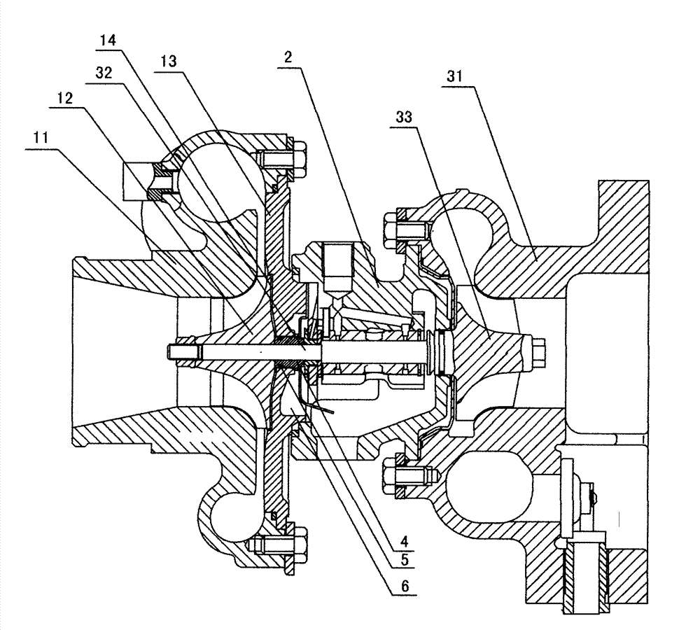
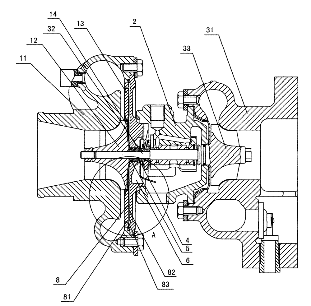
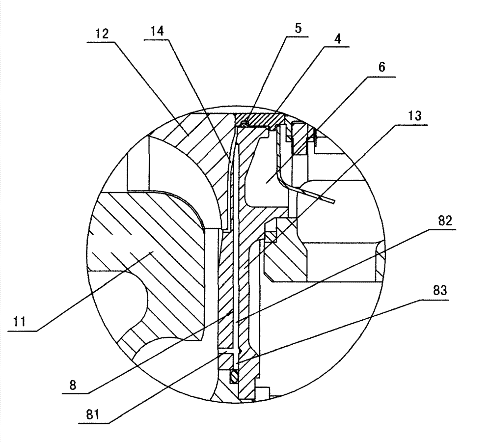
[0022] A kind of turbocharger that the present invention proposes, as figure 2 and image 3 As shown, it includes a compressor casing 11, an intermediate body 2 and a turbine casing 31 connected together, a turbine shaft 32 is installed in rotation in the intermediate body 2, and a compressor impeller 12 is fixed on one end of the turbine shaft 32, and the compressor impeller 12 is set In the compressor casing 11, the compressor wheel 12 and the compressor casing 11 constitute a centrifugal compressor, the other end of the turbine shaft 32 is fixed with a turbine 33, the turbine 33 is arranged in the turbine casing 31, and the shaft seal 4 is set on the turbine shaft 32 , one shaft end of the shaft seal sleeve 4 is in contact with the wheel back of the compressor impeller 12, the shaft seal sleeve 4 is covered with a compressor back plate 13...


PUM


Abstract

The invention discloses a turbocharger which comprises a compressor casing, an intermediate body and a turbine casing. A turbine rotating shaft is installed inside the intermediate body. A compressor impeller is fixed at one end of the turbine rotating shaft. A shaft sleeve is sleeved on the turbine rotating shaft. One end of the shaft sleeve contacts the impeller back of the compressor impeller. A compressor back plate is sleeved outside the shaft sleeve. An impeller back gap exists between the impeller back of the compressor impeller and the compressor back plate. Two air through holes are formed in the compressor back plate in an axial symmetry mode. A first end of each air through hole faces the compressor casing. A second end of each air through hole faces the impeller back of the compressor impeller, and is communicated with the impeller back gap. The turbocharger has the advantages that when the turbocharger is in normal work, the pressure of air at the position of the first end of each air through hole is higher than the pressure of air nearby the center of the impeller back of the compressor impeller. Therefore, air can flow to the position of the impeller back of the compressor impeller through the air through holes. The negative pressure at the position of the impeller back of the compressor impeller is reduced, and therefore lubricating oil in a lubricating oil chamber is effectively prevented from being sucked out.

Description

technical field [0001] The invention relates to a supercharger, in particular to a turbocharger. Background technique [0002] Because turbochargers have the characteristics of improving engine power, reducing fuel consumption, and reducing emissions, they are currently widely used in engines (including gasoline engines and diesel engines). However, the oil leakage problem of the turbocharger is the most concerned issue in the industry. The oil leakage problem accounts for more than 80% of turbocharger failures, and most of the oil leakage problems occur at the compressor end of the turbocharger. [0003] The sealing structure at the compressor end of the existing turbocharger mostly adopts a double seal ring or a single seal ring with a small gap and an oil baffle structure. figure 1 A cross-sectional structure of a common turbocharger is given. The turbocharger includes a compressor casing 11 connected together, an intermediate body 2 and a turbine casing 31, and a turbin...

Claims


Application Information

Patent Timeline
IPC IPC(8): F02B37/00F02B39/14
CPCY02T10/12
Inventor 马国山袁跃宏王瑞坤
Owner NINGBO WEIFU TIANLI TURBOCHARGING TECH
Why Eureka
Try Eureka