Gas suction structure of compressor

A compressor and cylinder technology, applied in the field of compressor suction structure, can solve problems such as turbulent flow, reduction of effective volume of cylinder, insufficient heating capacity of compressor, etc.

Active Publication Date: 2013-06-26
GREE ELECTRIC APPLIANCES INC +1
View PDF12 Cites 9 Cited by
  • Summary
  • Abstract
  • Description
  • Claims
  • Application Information

AI Technical Summary

Problems solved by technology

like figure 1 and figure 2 As shown, the existing cylinder suction hole x is all set in the middle of the cylinder inner wall (vertical axial direction), and the suction hole x is a circular hole directly connected to the cylinder, and when the cylinder sucks air, it will The demand for gas in the direction of the straight axis is uniform, so turbulent flow occurs after the gas is sucked into the cylinder, resulting in increased suction resistance and additional vibration and noise; in addition, when the compressor is working, only when the rolling When the sub covers the suction hole x, the roller rotates counterclockwise figure 2 Only when the point A is in the middle, the cylinder can effectively inhale air; in order to ensure sufficient air inhalation for the compressor, the air inlet should not be too small, and the circular inhalation hole x will cause figure 2 The α angle in the middle is relatively large, which reduces the effective volume of the cylinder, which will cause the problem of insufficient heating capacity of the compressor, especially when the frequency conversion compressor is running at high frequency.

Method used


Image

  • Gas suction structure of compressor
  • Gas suction structure of compressor
  • Gas suction structure of compressor

Examples


Embodiment 1

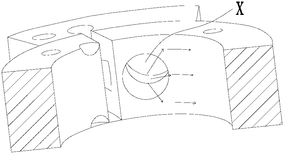
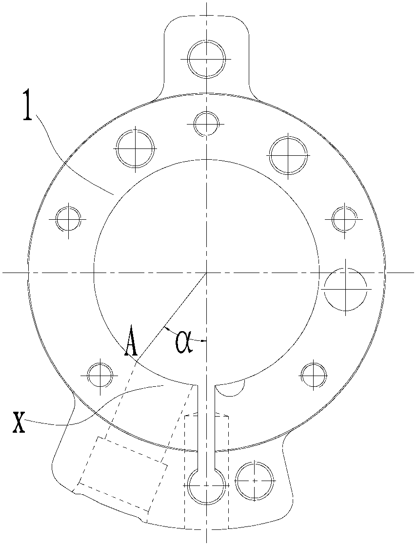
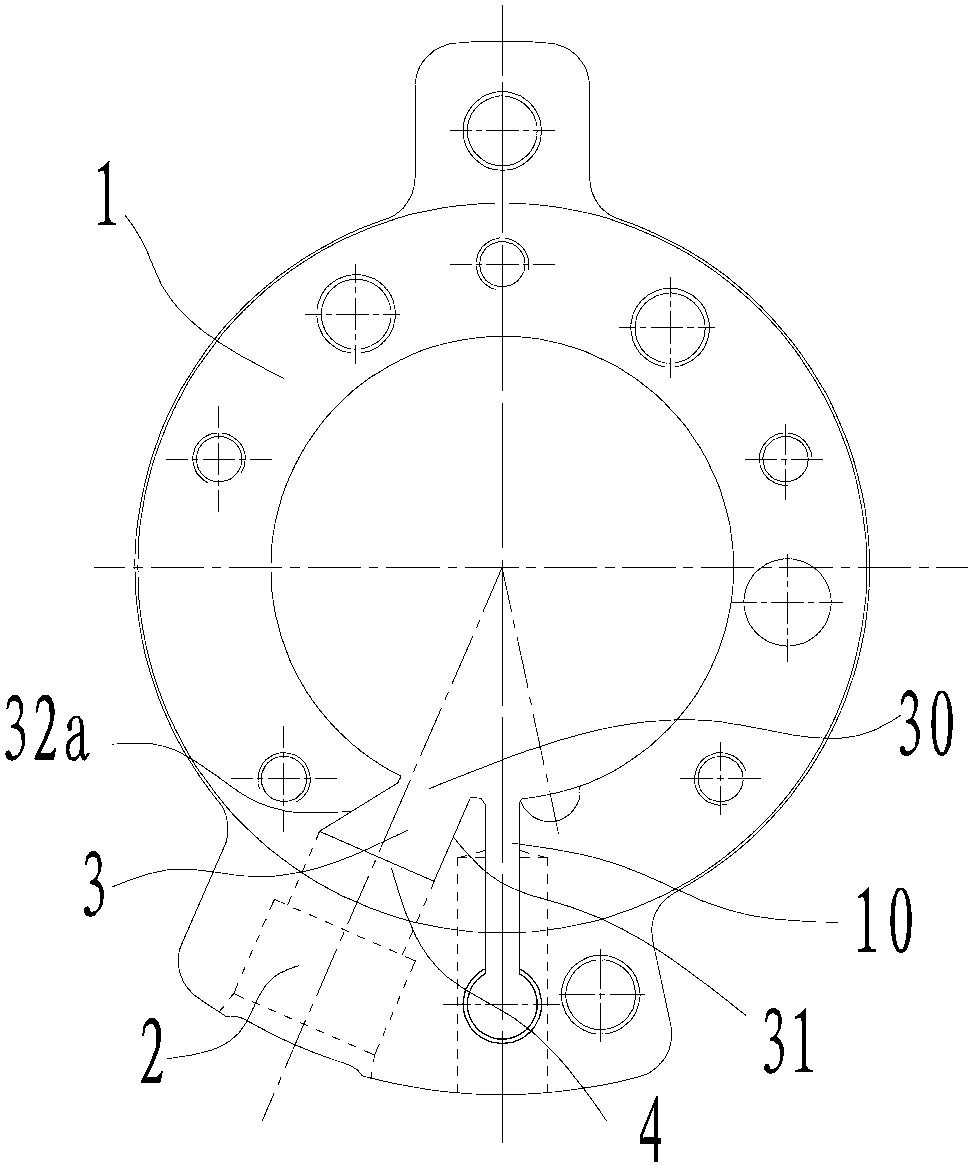
[0027] A suction structure of a compressor, such as image 3 As shown, it includes the air intake channel 2 opened radially on the cylinder 1, and also includes: a suction port formed on the inner wall side of the cylinder 1 along the axial direction of the cylinder 1, which passes through the two ends of the cylinder and communicates with the air intake channel 2 and is vertically arranged. Channel 3, the air inlet of the suction channel 3 on the inner wall of the cylinder is a rectangular air inlet 30 formed along the axial direction of the cylinder through the two ends of the cylinder, and the rectangular air inlet 30 is close to the slide slot 10 of the cylinder 1 Set, the rectangular air inlet 30 is a rectangular hole with a narrow horizontal direction and a long vertical direction; the diameter of the connecting port 4 of the suction channel 3 and the air intake channel 2 to the rectangular air inlet 30 gradually becomes smaller, and the suction The channel 3 near the si...

Embodiment 2

[0029] Such as Figure 4 to Figure 6 As shown, the difference from Embodiment 1 is that the side of the suction channel 3 away from the slide groove 10 forms an obtuse-angled vertical channel surface 32b that passes through the two ends of the cylinder 1 and consists of two connecting sections. A section of the passage surface 32b is flush with the inner edge of the air intake passage and is arranged parallel to the radial centerline of the air intake passage. Tilt setting.

Embodiment 3

[0031] Such as Figure 7 As shown, the difference from Embodiment 1 is that the suction passage 3 is away from the sliding vane groove 10 and forms an arc-shaped vertical passage surface 32c that passes through both ends of the cylinder 1 and smoothly connects with the rectangular air inlet 30 in an arc shape. This facilitates the smooth transition of the gas flowing out from the air intake passage to the rectangular air intake 30 .


PUM


Abstract

The invention discloses a gas suction structure of a compressor. The structure comprises a gas inlet channel provided radially on a gas cylinder. The structure also comprises a suction channel which is formed on the inner side of the gas cylinder along a gas cylinder axial direction. The suction channel penetrates the two end faces of the gas cylinder. The suction channel communicates with the gas inlet channel, and is arranged vertically. The gas inlet of the suction channel on the inner wall of the gas cylinder is a rectangular gas inlet formed on the axial direction of the gas cylinder and penetrating the two end faces of the gas cylinder. The rectangular gas inlet is arranged close to a sliding vane groove of the gas cylinder. The suction channel is convenient to manufacture. Also, with the suction channel, gas cylinder suction volume can be increased, a relatively ample buffer space is provided, such that suction resistance can be reduced, and gas can flow into the gas cylinder more smoothly.

Description

【Technical field】 [0001] The invention relates to compressor equipment, in particular to a compressor suction structure. 【Background technique】 [0002] A rotary compressor generally includes a closed casing, a cylinder, an upper bearing, a lower bearing, a crankshaft, a motor, sliding vanes, rollers, etc. The airtight casing is provided with a suction pipe and an exhaust pipe, the cylinder is set in the airtight casing, the upper and lower bearings are arranged at the upper and lower ends of the cylinder, the air suction port and the exhaust port are opened on the cylinder, and the rollers are installed in the airtight casing. On the eccentric crankshaft, the roller rolls along the inner wall of the cylinder during operation, and the slide piece is installed in the slide piece groove opened on the cylinder. When the roller rolls in the working chamber, the front end of the slide piece is kept in contact with the roller under the action of the spring The outer circle is in ...

Claims


Application Information

Patent Timeline
Patent Type & Authority Applications(China)
IPC IPC(8): F04C29/12
Inventor 刘达炜
Owner GREE ELECTRIC APPLIANCES INC
Why Eureka
Try Eureka