PM1 (Particulate Matter) jointed multi-level cutting sampling head

A sampling head and conjoined technology, which is applied in the field of PM1 conjoined multi-stage cutting sampling head, can solve the problems of inability to achieve graded collection of particulate matter, small size, limited range, etc., and achieve safety and aesthetics, cutting particle size Accurate, collection efficiency-enhancing effects

Inactive Publication Date: 2015-06-17
FOSHAN ENVIRONMENTAL PROTECTION TECH & EQUIP RES DEV PROFESSIONAL CENT
View PDF7 Cites 0 Cited by
  • Summary
  • Abstract
  • Description
  • Claims
  • Application Information

AI Technical Summary

Problems solved by technology

Due to the relatively late start of research on aerosol particles in my country, most of the aerosol particle sampling equipment used by the domestic environmental protection department is imported from abroad. The domestic design and production of aerosol multi-stage collection equipment is weak, and there is no strong competition. capacity, its measuring range (100L / Min or 1000L / Min) is limited; MOUDIMMI, Andersen eight-stage impact sampler Sioutas Cascade Impactor (SKC), which is more commonly used in the world, has a flow rate of only 9L / min-90L / min, and The volume is small, which is far from meeting the sample volume required for the analysis of granular POPs
In addition, none of these multi-stage samplers can simultaneously collect gaseous POPs
However, the large-flow samplers commonly used in atmospheric POPs research can collect particulate and gaseous pollutants at the same time, but the collected particulate matter is basically total suspended particulate matter (TSP), which cannot achieve classified collection of particulate matter.
It is also impossible to realize automatic control, and the flow stability and accuracy are not ideal

Method used


Image

  • PM1 (Particulate Matter) jointed multi-level cutting sampling head
  • PM1 (Particulate Matter) jointed multi-level cutting sampling head
  • PM1 (Particulate Matter) jointed multi-level cutting sampling head

Examples


Embodiment Construction

[0034] In order to make the object, technical solution and advantages of the present invention clearer, the present invention will be further described in detail below in conjunction with the accompanying drawings.

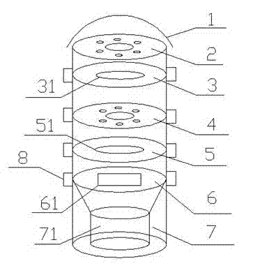
[0035] Such as Figure 1-Figure 4 As shown, a PM1 conjoined multi-stage cutting sampling head, the PM1 conjoined multi-stage cutting sampling head is a layered combination structure, mainly composed of cutting mouth cover 1, PM2.5 impact nozzle layer 2, PM2 from top to bottom .5 impact plate layer 3, PM1 impact nozzle layer 4, PM1 impact plate layer 5, filter membrane collection layer 6, PUF collection layer composition 7,

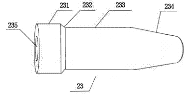
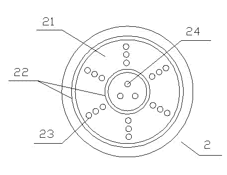
[0036] The PM2.5 impact nozzle layer 2 and the PM1 impact nozzle layer 4 both include an impact nozzle plate and at least one group of impact nozzles 23 arranged in an equidistant circular arrangement on different diameters on the impact nozzle plate;

[0037] The upper end of the impact nozzle 23 is a first cylinder 231; the middle part of t...


PUM

PropertyMeasurementUnit
heightaaaaaaaaaa
heightaaaaaaaaaa
heightaaaaaaaaaa

Abstract

The embodiment of the invention discloses a PM1 (Particulate Matter) jointed multi-level cutting sampling head. The PM1 jointed multi-level cutting sampling head adopts a laminar combined structure and comprises a cutting port cover, a PM2.5 impacting port layer, a PM2.5 impacting plate layer, a PM1 impacting port layer, a PM1 impacting plate layer, a filter membrane collecting layer and a PUF (Polyurethane Foam) collecting layer which are respectively formed from top to bottom. According to the PM1 jointed multi-level cutting sampling head, the design flow rate can reach 300L / Min, thus the actual demands of the sampling process to the flow rate and the sampling time can be met; and the PM1 aerosol particles and gaseous pollutants can be collected at the same time, so that the graded collection of the particulate matters can be realized, and the automatic control is realized under the premise that the stability and accuracy of the flow rate are met. The cutting power cover adopts circular arc shape design, thus the gas can circle round and flow into a cutting head, and as a result, the stability and the uniformity of the collected gas flow are improved.

Description

technical field [0001] The invention relates to a cutting and sampling head, in particular to a PM1 conjoined multi-stage cutting and sampling head. Background technique [0002] PM1 refers to particles with an aerodynamic equivalent diameter of ≤1 μm. Among inhalable particulates (inhalable particulates), PM1 can be inhaled deep into the lungs of the human body through the respiratory system, and is more harmful to human health. As a part of inhalable particulate matter in the air, PM1 should be used as an independent air quality evaluation index in the field of environmental monitoring. [0003] The impact cutting technology is mainly used in the hierarchical collection technology of atmospheric particulate matter, that is, the inertial impact principle is used to conduct hierarchical sampling of particulate matter, and at the same time to collect PM1 and gaseous persistent organic pollutants (POPs for short), it is necessary to adopt multi-level multi-functional sampling....

Claims


Application Information

Patent Timeline
Patent Type & Authority Patents(China)
IPC IPC(8): G01N1/22G01N1/10
Inventor 张干李军邹世春
Owner FOSHAN ENVIRONMENTAL PROTECTION TECH & EQUIP RES DEV PROFESSIONAL CENT
Why Eureka
Try Eureka