Touch sensor with reduced anti-touch effects

A technology of touch sensor and sensing line, applied in the direction of instrument, input/output process of data processing, pulse technology, etc., can solve the problem of not alleviating the anti-touch effect

Inactive Publication Date: 2013-06-26
NEODRON LTD
View PDF7 Cites 6 Cited by
  • Summary
  • Abstract
  • Description
  • Claims
  • Application Information

AI Technical Summary

Problems solved by technology

For example, electrode patterns using the standard double d

Method used


Image

  • Touch sensor with reduced anti-touch effects
  • Touch sensor with reduced anti-touch effects
  • Touch sensor with reduced anti-touch effects

Examples


Embodiment Construction

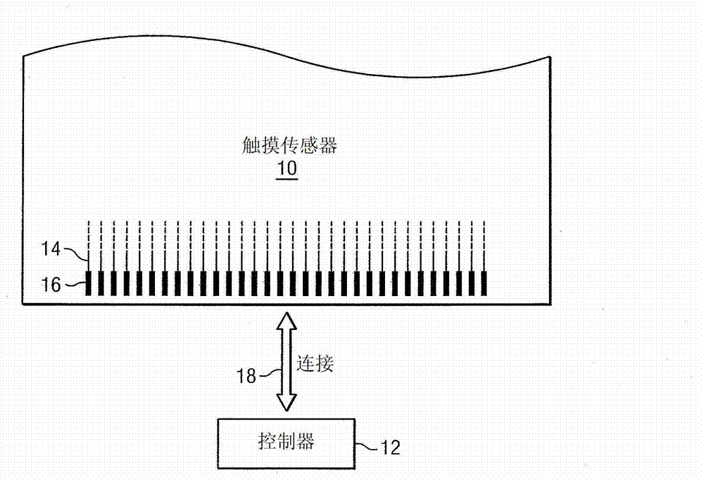
[0024] figure 1 An example touch sensor 10 is illustrated with an example touch sensor controller 12 . Touch sensor 10 and touch-sensor controller 12 can detect the presence and location of a touch or proximity of an object within the touch-sensitive area of ​​touch sensor 10 . Herein, a reference to a touch sensor may encompass both the touch sensor and its touch sensor controller, where appropriate. Similarly, reference to a touch-sensor controller may encompass both the touch-sensor controller and its touch sensors, where appropriate. Touch sensor 10 may include one or more touch-sensitive areas, where appropriate. Touch sensor 10 may include an array of drive and sense electrodes (or an array of electrodes of a single type) disposed on one or more substrates, which may be made of a dielectric material. Herein, references to a touch sensor may encompass both the electrodes of the touch sensor and the substrate on which the electrodes are disposed, where appropriate. Alt...


PUM


Abstract

The present invention relates to a touch sensor with reduced anti-touch effects. In an embodiment, a system comprises a touch sensor. The touch sensor comprises an insulating substrate and a plurality of electrodes disposed on the insulating substrate. The plurality of electrodes comprises a drive line having a plurality of drive electrodes and a sense line having a plurality of sense electrodes. At least one of the electrodes comprises a first conductive material having a hole portion substantially free of the first conductive material.

Description

technical field [0001] The present invention generally relates to touch sensors. Background technique [0002] For example, a touch sensor may detect the presence and location of a touch or proximity of an object, such as a user's finger or stylus, within a touch sensitive area of ​​the touch sensor overlaid on the display screen. In touch-sensitive display applications, touch sensors may enable users to interact directly with content displayed on the screen rather than indirectly with the aid of a mouse or touch pad. Touch sensors can be attached to or provided as part of: desktop computers, laptop computers, tablet computers, personal digital assistants (PDAs), smartphones, satellite navigation devices, portable media players , portable game console, kiosk computer, point of sale device, or other suitable device. Control panels on home appliances or other appliances may contain touch sensors. [0003] There are different types of touch sensors such as, for example, resi...

Claims


Application Information

Patent Timeline
IPC IPC(8): G06F3/041
CPCG06F3/0443G06F3/0446H03K17/9622H03K2017/9602
Inventor 马修·特伦德萨米埃尔·布吕内戴维·B·格尔德卢本·H·赫里斯托夫
Owner NEODRON LTD
Why Eureka
Try Eureka