Calibrating method for two-dimensional laser and camera without overlapped viewing fields

A two-dimensional laser and calibration method technology, applied in image data processing, instruments, calculations, etc., can solve problems such as low precision, limited placement of cameras and laser scanners, and high cost of manual selection, etc., to achieve high Calibration accuracy, large field of view, and the effect of improving the degree of automation

Inactive Publication Date: 2013-06-26
BEIJING UNIV OF POSTS & TELECOMM
View PDF0 Cites 23 Cited by
  • Summary
  • Abstract
  • Description
  • Claims
  • Application Information

AI Technical Summary

Problems solved by technology

[0006] 2. The selection of matching pairs depends on manual selection, the human error introduced cannot be well counted and controlled, and the accuracy is low. At the same time, manual selection takes a lot of tim...

Method used


Image

  • Calibrating method for two-dimensional laser and camera without overlapped viewing fields
  • Calibrating method for two-dimensional laser and camera without overlapped viewing fields
  • Calibrating method for two-dimensional laser and camera without overlapped viewing fields

Examples


Embodiment Construction

[0031] The present invention will be further described below in conjunction with the drawings.

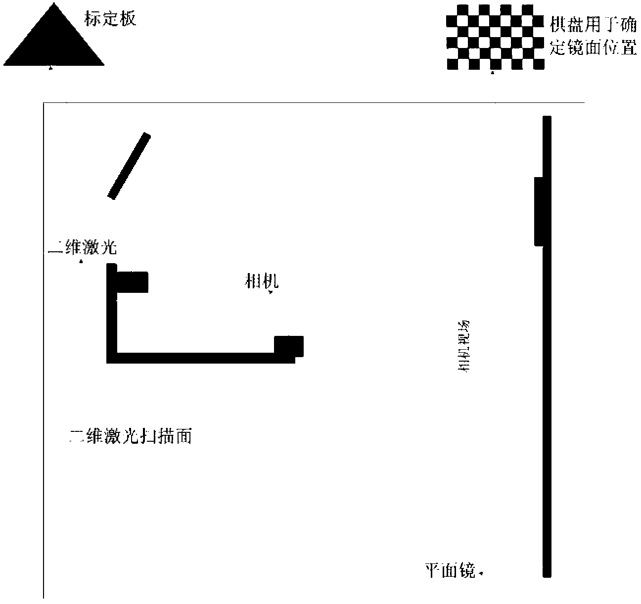
[0032] Such as figure 1 Shown is the composition diagram of the camera and two-dimensional laser calibration system of the present invention. The system mainly includes: two-dimensional laser scanner, camera, plane mirror, etc.

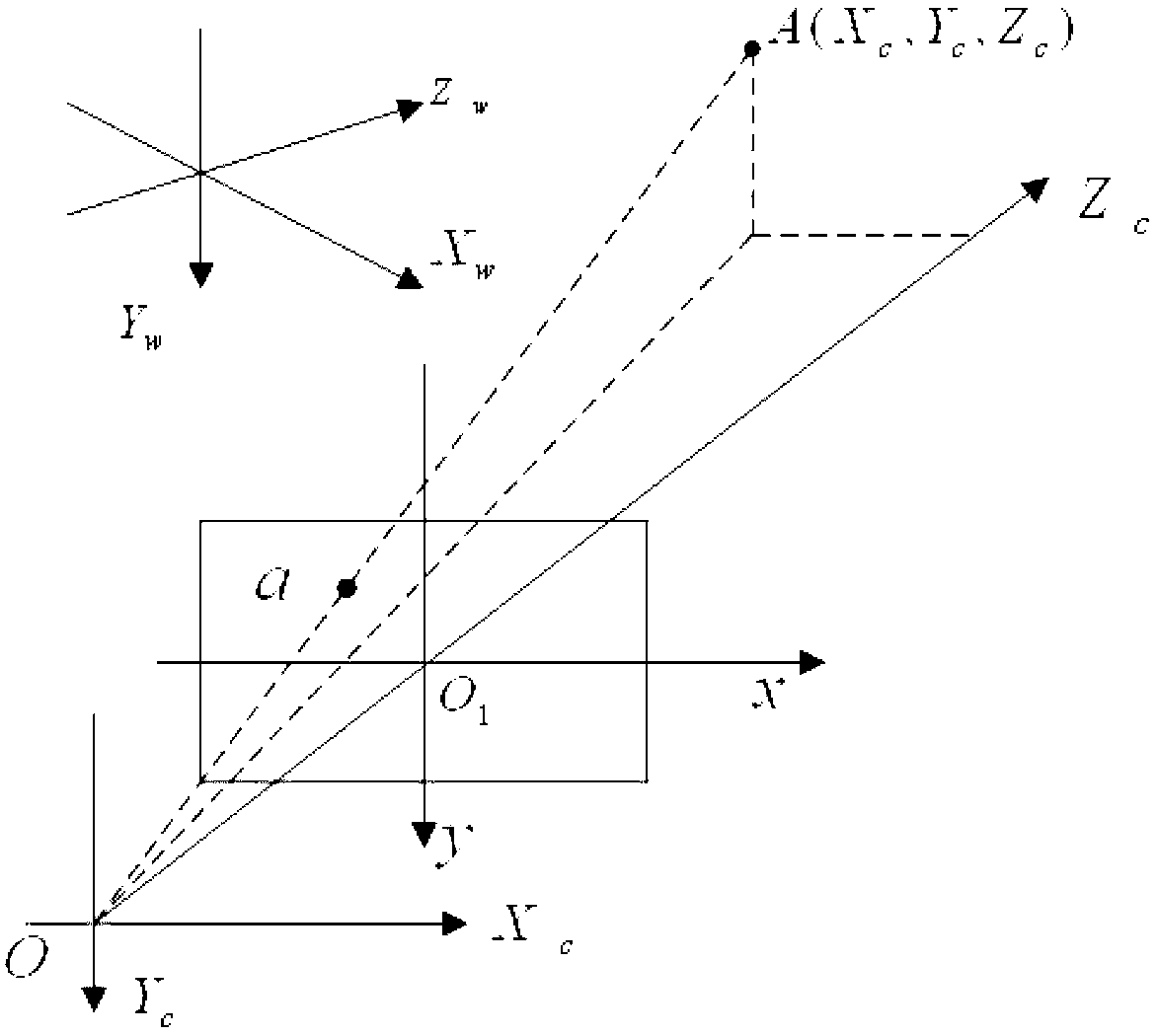
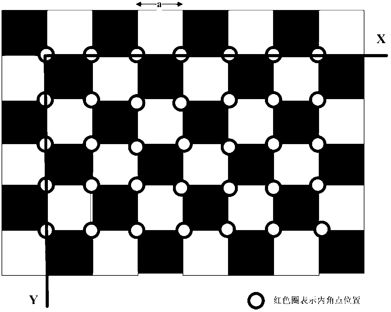
[0033] Step 1: Use the pinhole camera model to consider the lens distortion factor, and use the traditional checkerboard table to calibrate the camera's internal parameters. In the image plane, the upper left corner is the coordinate origin, the horizontal direction is the u axis, the vertical direction is the v axis, and the unit is pixel. Since the rectangular coordinate system uv only represents the number of rows and columns of pixels in the digital image, However, the position of the pixel in the image is not expressed in physical units, and a coordinate system xy expressed in physical units needs to be established. (x, y) represents the coordinates of th...


PUM


Abstract

The invention discloses a calibrating method for two-dimensional laser and a camera without overlapped viewing fields. A calibrating system comprises a two-dimensional laser scanner, the camera, a plane mirror and the like. The calibrating method includes calibrating intrinsic parameters of the camera by the aid of the traditional chessboard table via a pinhole camera model; reasonably configuring the laser scanner, the camera and the plane mirror, adhering the black and white chessboard table on the plane mirror, locating the chessboard table within the range of a viewing field of the camera and determining a transformation matrix between a coordinate system of the chessboard and a coordinate system of the camera; determining a transformation relation between the coordinate system of the chessboard and a coordinate system of a camera image reflected in the mirror according to a symmetric relation of mirror surface images so as to acquire a transformation relation between the actual camera and the camera image reflected in the mirror; performing observation at selected sufficient frequency by changing the position and gestures of a black triangular calibrating plate to acquire sufficient observation samples, estimating by a Gauss-Newton iterative process to acquire a transformation matrix between the coordinate system of the camera image and the two-dimensional laser scanner; and acquiring a rotation and translation transformation matrix between the coordinate system of the camera and a coordinate system of the two-dimensional laser scanner via relations between positions and gestures of the camera and the camera image and relations between positions and gestures of the camera image and the two-dimensional laser scanner.

Description

Technical field [0001] The invention relates to the calibration of a camera and a two-dimensional laser in the field of multi-sensor data fusion. Background technique [0002] In the visual navigation of intelligent robots, the use of multi-sensor fusion technology can obtain a more reliable, uniform and detailed description of the environment for decision-making, planning and control. When performing data fusion, multi-sensor calibration is one of the problems that must be solved. The calibration is generally divided into the calibration of each sensor's own parameters and the joint calibration of multiple sensors. The calibration of each sensor's own parameters is to ensure the accuracy of the collected data, and the joint calibration of multiple sensors is to accurately match the data of multiple sensors. [0003] In the technology of camera and 2D laser scanner data fusion, the joint calibration of camera and 2D laser is a crucial link. The vision sensor has a wide detection...

Claims


Application Information

Patent Timeline
IPC IPC(8): G06T7/00
Inventor 叶平孙汉旭贾庆轩杜宇楠窦仁银
Owner BEIJING UNIV OF POSTS & TELECOMM
Why Eureka
Try Eureka