Radiation structure of wind driven generator

A technology of wind turbines and heat dissipation structures, which is applied in wind power generation, electrical components, electromechanical devices, etc., can solve the problem of motor heat dissipation without other auxiliary functions.

Inactive Publication Date: 2013-06-26
BEIJING GOLDWIND SCI & CREATION WINDPOWER EQUIP CO LTD
View PDF5 Cites 3 Cited by
  • Summary
  • Abstract
  • Description
  • Claims
  • Application Information

AI Technical Summary

Problems solved by technology

That is to say, the existing heat dissipation pipes only have the function of conveying hot air, and have no other auxiliary effect on the heat dissipation of the motor

Method used


Image

  • Radiation structure of wind driven generator
  • Radiation structure of wind driven generator
  • Radiation structure of wind driven generator

Examples


Embodiment Construction

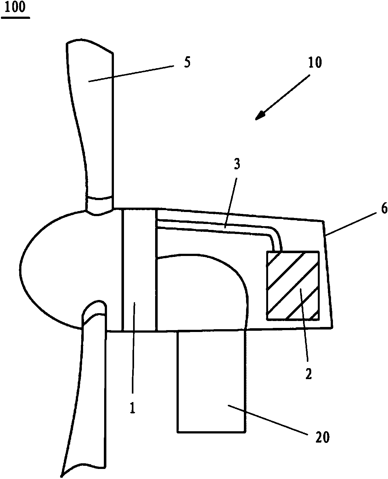
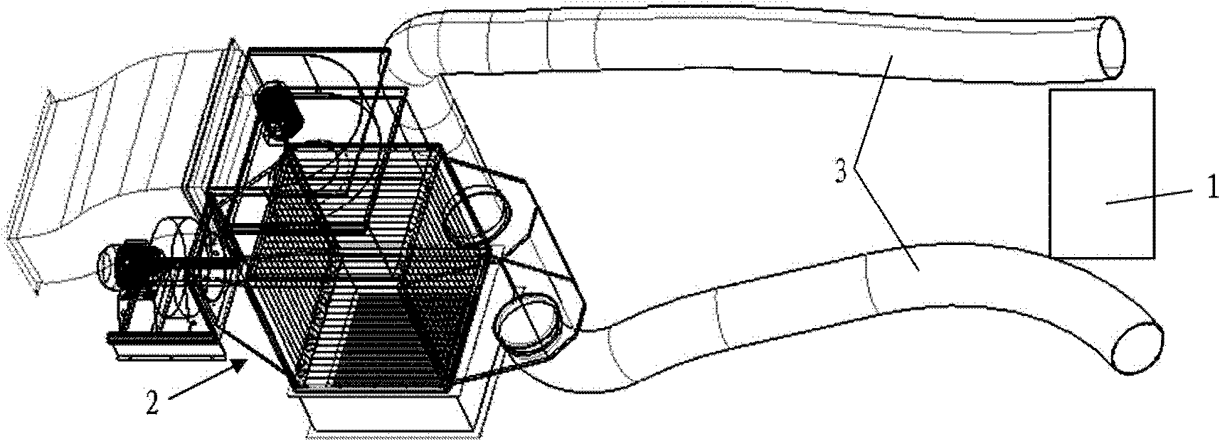
[0026] Such as image 3 As shown, the heat dissipation structure of the wind power generator according to the embodiment of the present invention includes a radiator 2 and at least one heat dissipation pipe 3 . The radiator 2 is arranged on one side of the nacelle, and the generator 1 is arranged on the other side of the nacelle. One end of the heat dissipation pipe 3 is connected with the radiator 2 and the other end is connected with the generator 1 .

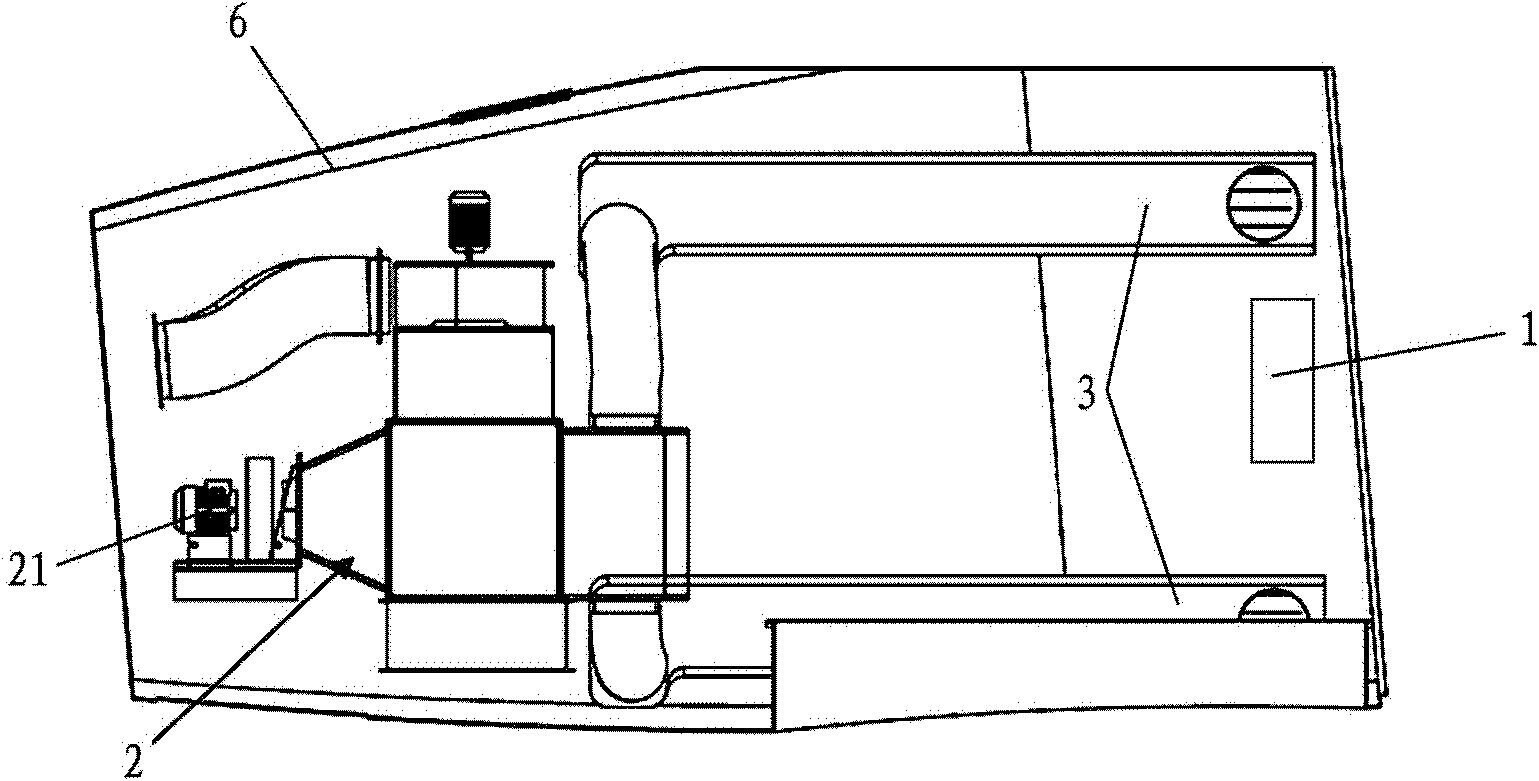
[0027] The radiator 2 has a motor 21 for delivering the hot air generated in the generator 1 to the radiator 2 via the heat dissipation pipe 3 .

[0028] The following will combine Figure 4 The specific structure of the heat dissipation pipe 3 will be described in detail.

[0029] The heat dissipation duct 3 includes two parts that are combined with each other to form a cavity, wherein one part is the cabin wall 6 and the other part is the cover plate 32 . That is, the heat dissipation passage 3 is formed by combining th...


PUM


Abstract

The invention discloses a radiation structure of a wind driven generator. The generator located on one side in a wind driven generator cabin is connected with a radiator located on the other side in the cabin through a radiating pipe, and one part of the radiating pipe is formed by a part of the cabin. The radiating pipe of the radiation structure cannot excessively occupy the effective space in the cabin and cannot swing along with rotating of a hand piece. The radiation structure of the wind driven generator can further improve the radiating efficiency.

Description

technical field [0001] The present invention relates to a wind power generator, more specifically, to a heat dissipation structure of a wind power generator. Background technique [0002] The generator of the wind power generating set generates heat during operation, and the heat generated by the motor should be evacuated in time. If heat accumulates inside the motor, it will cause the internal temperature of the motor to rise, resulting in damage to the insulation of the motor coil. In addition, for permanent magnet generators, temperature rise will affect the magnetic coercive force characteristics of the magnetic steel inside the motor and reduce the efficiency of the generator. Small-power motors generate less heat, and air cooling can meet the heat dissipation requirements without installing a radiator. However, high-power motors generate more heat, and air cooling cannot meet heat dissipation requirements, and radiators need to be added to assist heat dissipation. ...

Claims


Application Information

Patent Timeline
Patent Type & Authority Applications(China)
IPC IPC(8): H02K9/10
CPCY02E10/72
Inventor 孙涛
Owner BEIJING GOLDWIND SCI & CREATION WINDPOWER EQUIP CO LTD
Why Eureka
Try Eureka