
Method for rounding honing bar by utilizing honing head

A technology of honing heads and honing sticks, which is applied in the field of honing processing, can solve the problems of a large number of parts, aggravate the vibration of the outer diameter of the honing sticks, and the axial dimension is too long, so as to improve the accuracy of the circle, avoid adverse effects, and prevent the accuracy of effect of loss

Active Publication Date: 2015-04-01
上海达特精密机械配件有限公司 +1
View PDF9 Cites 0 Cited by
  • Summary
  • Abstract
  • Description
  • Claims
  • Application Information

AI Technical Summary

Problems solved by technology

This honing head circular device is attached to the original honing head along the axial direction, so two problems can be produced: one, the axial dimension of the whole device including the honing head and the circular device is too long, the rigidity is poor, Two, the number of parts is large, and the clearance is large
The above two problems will aggravate the vibration of the outer diameter of the honing stick when it is round, and cannot guarantee the roundness accuracy of the honing stick

Method used


Image

  • Method for rounding honing bar by utilizing honing head
  • Method for rounding honing bar by utilizing honing head
  • Method for rounding honing bar by utilizing honing head

Examples


Embodiment 1

[0024] Embodiment 1: Gauging a single-feed honing head

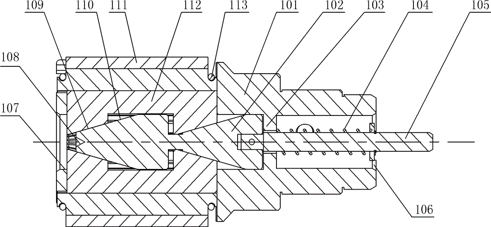
[0025] Such as figure 1 As shown, the single-feed honing head includes a hollow cylindrical honing head body 101 with a central hole 107 at the front end and a central hole 106 at the rear end of the honing head body 101 . The honing head body 101 is provided with an expanding mandrel 102 that can slide axially, and the inner wall of the honing head body 101 is provided with a retaining wall 103 for limiting the sliding range of the expanding mandrel 102 . The front end of the expansion mandrel 102 is provided with a central hole 108, and the central hole 108 is on the same axis as the central hole 107 and the central hole 106. The rear end of the expansion mandrel 102 is detachably connected with a push rod 105, the push rod 105 is covered with a return spring 104, and a plurality of honing rod bases 112 are arranged on the honing head body 101 along the circumferential direction, and the honing rod base 112 It is con...

Embodiment 2

[0031] Embodiment 2: Gauging the double-feed honing head

[0032] The so-called double-feed honing head is to use diamond honing rods or CBN honing rods and other high-hardness honing rods for rough honing, and honing rods such as GC abrasives for fine honing processing. The honing head is not replaced but in the same process. When completed, install two types of honing sticks on the same honing head in advance.

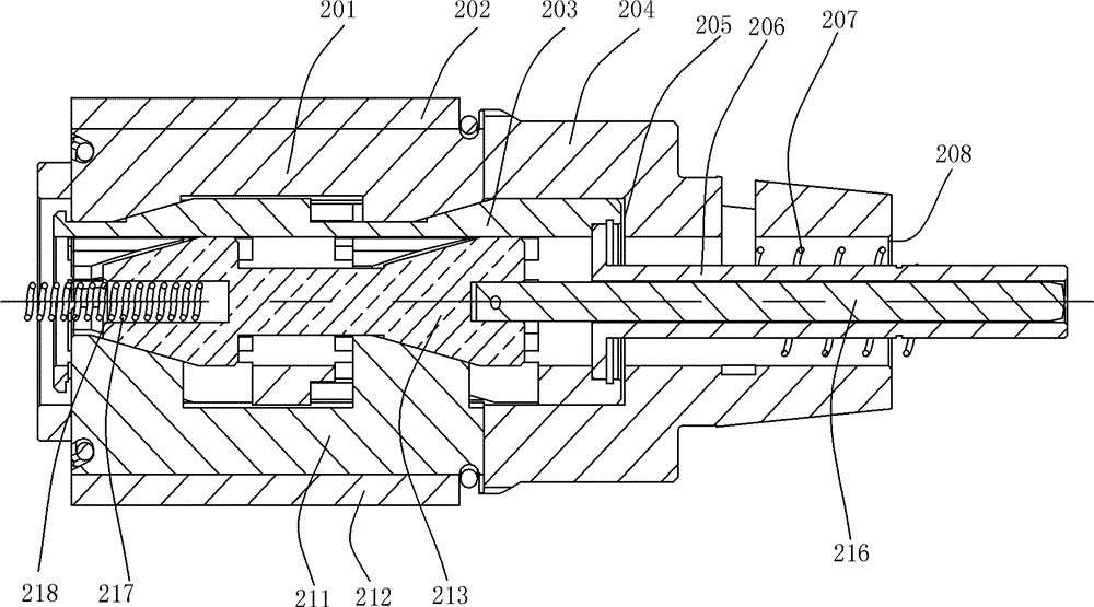
[0033] Such as image 3 As shown, the double-feed honing head includes a hollow cylindrical honing head body 204 , and the rear end of the honing head body 204 has a central hole 208 . There is a rough honing expansion mandrel 203 and a fine honing expansion mandrel 213 inside the honing head body 204, the rough honing expansion mandrel 203 is set on the outside of the fine honing expansion mandrel 213, the rough honing expansion mandrel 203 and the fine honing expansion mandrel 213 The expansion mandrels 213 can slide axially independently, and the inner wall of t...


PUM


Abstract

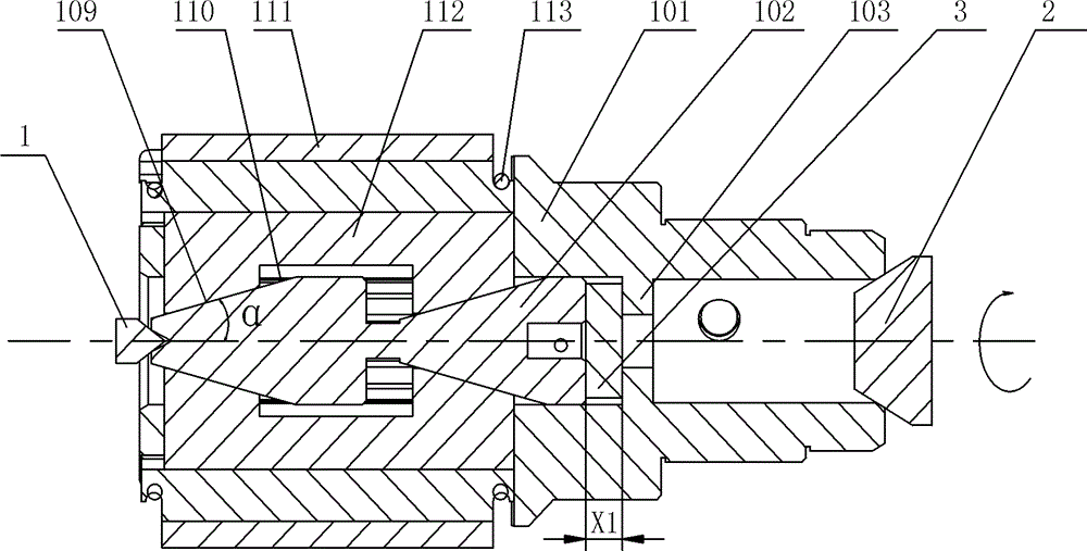
The invention discloses a method for rounding a honing bar by utilizing a honing head. An expansion core rod is arranged in a honing head body. When the expansion core rod slides forwards, the honing bar is expanded outwards. The rounding method comprises the following steps of: A, additionally arranging a cushion block at the rear end of the expansion core rod, enabling the expansion core rod to move forwards for a certain distance, and raising the honing bar from the surface of the honing head body; B, pressing a pressing device against the front end of the expansion core rod and the rear end of the honing head body respectively, and clamping the honing head; and C, enabling the honing head to rotate around an axis, and finishing the circumferential surface of the honing bar by utilizing a cutting tool. The honing head body can be used for the high-accuracy rounding of the honing bar, and restructuring operation over special tool parts is not required. The influence of fit clearances between a plurality of parts on the rotation of the honing head during rounding is eliminated. The mounting reference of the honing bar is consistent with the expansion reference of the honing bar, so that the accuracy of rounding when a high-hardness honing bar is used for the honing head is improved.

Description

technical field [0001] The invention relates to the technical field of honing processing, in particular to a method for rounding a honing stick on a honing head. Background technique [0002] In order to ensure the accuracy of the honing process, after the honing head is newly assembled or worn out, the honing stick needs to be rounded. [0003] Chinese utility model patent CN 200920244475.X discloses a honing honing stone gauge circle device, including a virtual honing head, the virtual honing head is mainly composed of three parts: a positioning mandrel, a clamp housing, and a locking back cap. There are top positioning holes at both ends of the clamp housing, clamp housing screws are installed on the clamp housing, the clamp housing and the positioning mandrel slide and fit, and are installed on the positioning mandrel, and the locking backs are installed at both ends of the positioning mandrel. The cap, the oil stone seat is installed in the clamp housing, and the oil s...

Claims


Application Information

Patent Timeline
Patent Type & Authority Patents(China)
IPC IPC(8): B24B53/12
Inventor 王苏毅张益黄少俊何军
Owner 上海达特精密机械配件有限公司
Learn More