A feed mechanism for an optoelectronic component testing machine

A technology for testing machines and feeding mechanisms, applied in the directions of conveyor objects, transportation and packaging, etc., can solve the problems of material jamming, narrow space for maintenance personnel activities, and restrictions, and achieve the problem of not easy material jamming and multi-design space. Effect

Active Publication Date: 2013-07-03
MPI CORP
View PDF7 Cites 3 Cited by
  • Summary
  • Abstract
  • Description
  • Claims
  • Application Information

AI Technical Summary

Problems solved by technology

Although the above-mentioned design can achieve the purpose of delivering materials, however, since the rotating device is located under the limited space at the front end of the buffer station, once the material is jammed and needs to be shut down for maintenance, the space for the maintenance personnel to move is relatively narrow, and the distance between the various components Occasionally, the installation and configuration relationship with the test machine will be subject to certain restrictions
Secondly, the materials are pushed against each other in the buffer station. Therefore, this design of taking the materials from the bottom of the buffer station is easy to cause the phenomenon of material jam

Method used


Image

  • A feed mechanism for an optoelectronic component testing machine
  • A feed mechanism for an optoelectronic component testing machine
  • A feed mechanism for an optoelectronic component testing machine

Examples


Embodiment Construction

[0047] The structure and effect of the present invention will be described in detail by citing the following embodiments in conjunction with the accompanying drawings.

[0048] First, it must be stated that throughout the description of the present invention, and in the claims that follow, when it is mentioned that one member drives another member, it is meant that the member is driven directly or through other means such as a belt. component indirectly drives the other component. Likewise, when it is mentioned that a component is pivotally connected to or disposed on another component, it means that the component is directly or indirectly pivoted to or disposed on the other component through other components.

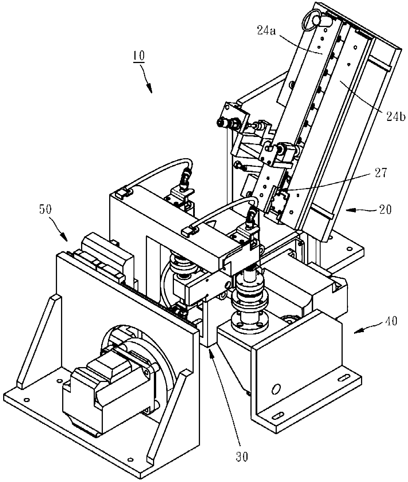
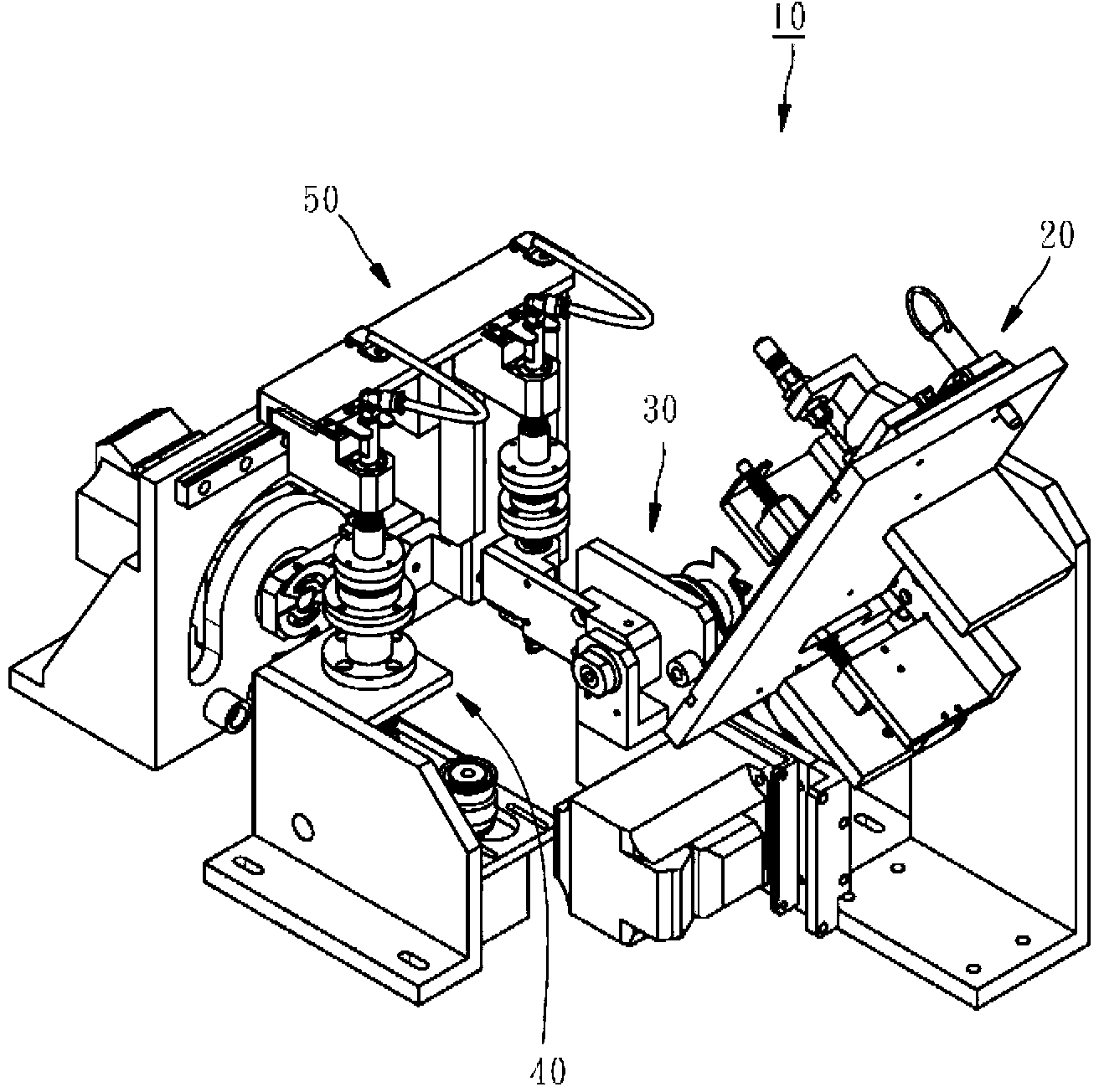
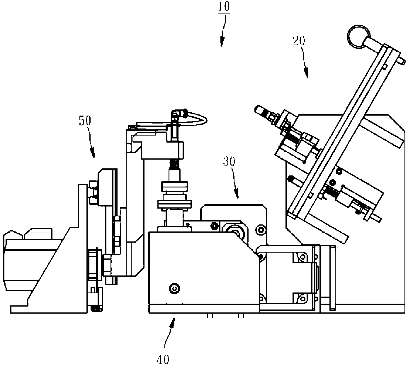
[0049] The main function of the feeding mechanism for the photoelectric component testing machine provided by the present invention is to deliver the material to be tested into a testing machine; wherein, the applicable material is such as (but not limited to) Optoele...


PUM


Abstract

The present invention relates to a feed mechanism for an optoelectronic component testing machine, which mainly comprises: a materials and parts column marshalling device, having an oblique arrangement to allow materials and parts arranged back face up slide to a materials and parts guide groove to-be-taken out position at one side by gravity; a materials and parts turnover device having a first materials and parts suction device which can suck up the materials and parts at the to-be-taken out position, and turn over the materials and parts to maintain a level posture face up; and a materials and parts picking and placing device having a second materials and parts suction device capable of delivering the turnover materials and parts in a face up manner to a feed position of the testing machine. The feed mechanism of the present invention allows the spatial arrangement of each component of the overall feeding mechanism more flexible and less clog

Description

technical field [0001] The present invention relates to a test machine for testing photoelectric components such as light-emitting diode (hereinafter referred to as LED) packaging modules, in particular to a feeding mechanism for the test machine of optoelectronic components. Background technique [0002] Most optoelectronic components such as light emitting diode (LED) single-chip packages or packaged modules need to undergo characteristic testing before leaving the factory, and the aforementioned optoelectronic components are classified by using parameters such as luminous intensity as judging criteria. Generally speaking, the aforementioned testing operation is completed by using an automatic feeding mechanism to deliver the material to be tested to a testing machine. [0003] Traditionally, the material to be tested is arranged in a material tube, and the material tube is tilted by lifting the end of the material tube, so that the material in the material tube can slide ...

Claims


Application Information

Patent Timeline
Patent Type & Authority Applications(China)
IPC IPC(8): B65G47/74B65G47/91B65G47/82
Inventor 李俊明洪伟恒
Owner MPI CORP
Why Eureka
Try Eureka