Filtration device

A filter device and filter tank technology, which is applied in the direction of filter circuit, filter separation, membrane filter, etc., can solve the problems of deformation of the mesh drum, and achieve the effect of simple structure, waste suppression, compactness and filter performance

Inactive Publication Date: 2013-07-03
BUNRI
View PDF10 Cites 8 Cited by
  • Summary
  • Abstract
  • Description
  • Claims
  • Application Information

AI Technical Summary

Problems solved by technology

The mesh roller d

Method used


Image

  • Filtration device
  • Filtration device
  • Filtration device

Examples


Embodiment Construction

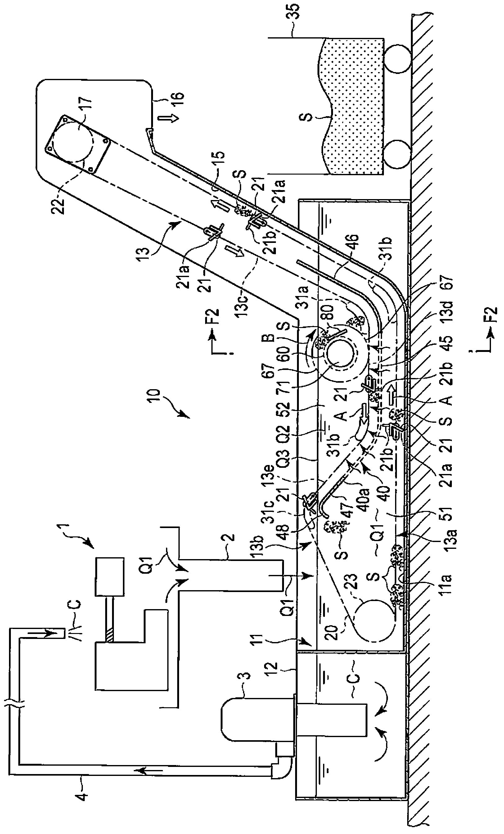
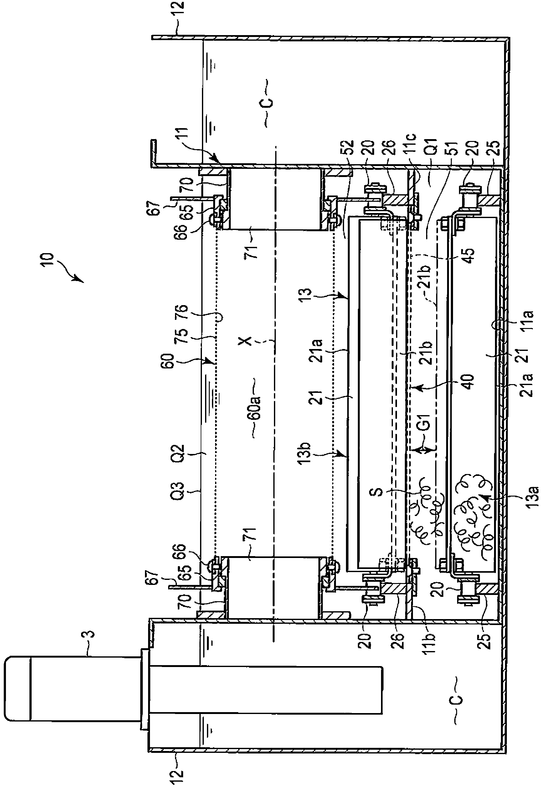
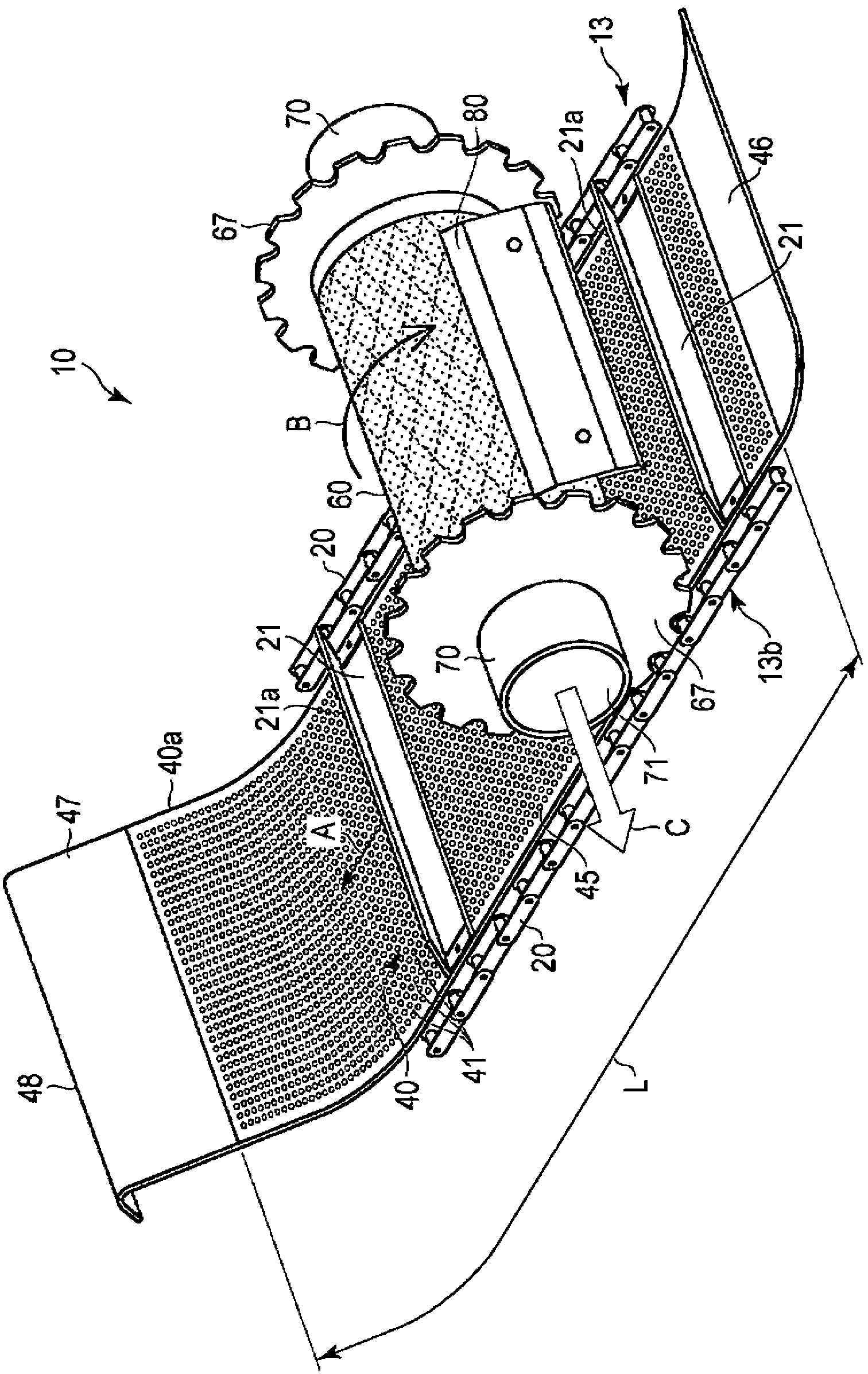
[0025] Refer to the following Figure 1 to Figure 7 A filter device according to one embodiment of the present invention will be described.

[0026] figure 1 A schematic configuration of a facility for removing foreign matter from a coolant (cutting fluid) used in a machine tool 1 such as a machining center is shown. The coolant discharged from the machine tool 1 is an example of the fluid Q1 to be filtered. In the treatment liquid Q1 , depending on the raw material to be processed, for example, scraps of aluminum alloys, magnesium alloys, iron-based metals, etc., non-metallic particles such as carbon, etc. generated by cutting etc. are mixed.

[0027] The processing liquid Q1 containing chips, fine particles, etc. flows from the machine tool 1 through the flow path 2 and is supplied to the filter device 10 . The treatment liquid Q1 is filtered once by the filter device 10 and becomes the treatment liquid Q2. Furthermore, the treatment liquid Q2 becomes the cleaning liquid...


PUM


Abstract

A filtration device (10) includes: a filtration tank (11); a conveyor (13) having a scraper (21); a first filter (40); and a cylindrical second filter (60) that rotates. The inside of the filtration tank (11) is divided into a first filtration tank portion (51) and a second filtration tank portion (52) by the first filter (40). A sludge (S) that has sunk to the bottom of the first filtration tank portion (51) is conveyed toward a sludge discharge portion (16) by a first portion (21a) of the scraper (21). A liquid (Q1) in the first filtration tank portion (51) is filtered by the first filter (40) and flows into the second filtration tank portion (52). A liquid (Q2) in the second filtration tank portion (52) is filtered by the second filter (60) and conveyed to a clean tank (12). The sludge (S) adhered to the second filter (60) is dropped on the first filter (40) and discharged toward the first filtration tank portion (51) by a second portion (21b) of the scraper (21).

Description

technical field [0001] The present invention relates to a filter device for purifying a treatment liquid mixed with, for example, chips and fine particles. Background technique [0002] A coolant (cutting fluid) is used to cool a workpiece or a tool in a machine tool that performs machining such as cutting or grinding. Chips (chips), fine particles, etc. are mixed in the coolant used in machining. In particular, in fields requiring weight reduction and corrosion resistance, since materials such as aluminum and magnesium are used, chips tend to diversify. In order to purify and reuse the coolant as described above, various filter devices have conventionally been proposed. [0003] For example, the filtration apparatuses disclosed in the following patent documents 1 and 2 include a filter tank, a scraper conveyor for sludge discharge, a mesh drum functioning as a filter, and the like. In addition, in order to prevent clogging of the mesh drum, cleaning liquid spray nozzles ...

Claims


Application Information

Patent Timeline
IPC IPC(8): B01D36/02B01D24/46B01D29/00B01D29/62B01D33/15B23Q11/00
CPCB01D33/04B01D33/073B01D33/37B01D33/466B01D33/76B01D2201/184B23Q11/1069B23Q11/0067Y02P70/10B01D36/02B01D29/64B01D21/24B01D33/15B01D33/46
Inventor 田代实
Owner BUNRI
Why Eureka
Try Eureka