Air spring device

An air spring and elastomer technology, applied in springs, low internal friction springs, springs/shock absorbers, etc., can solve the problems of reduced durability of elastic components and reduced durability of air spring devices, and achieves vertical spring constant and The effect of reducing the horizontal spring constant, ensuring ride comfort, and excellent ride comfort

Active Publication Date: 2013-07-03
BRIDGESTONE CORP
View PDF8 Cites 11 Cited by
  • Summary
  • Abstract
  • Description
  • Claims
  • Application Information

AI Technical Summary

Problems solved by technology

This causes a problem that contact occurs between the upper panel and the lower panel or between one of the upper panel and the lower pane

Method used


Image

  • Air spring device
  • Air spring device
  • Air spring device

Examples


Embodiment Construction

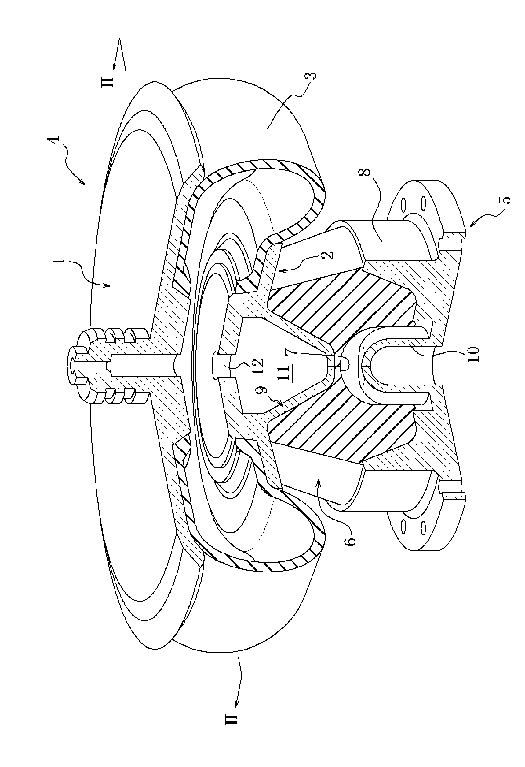
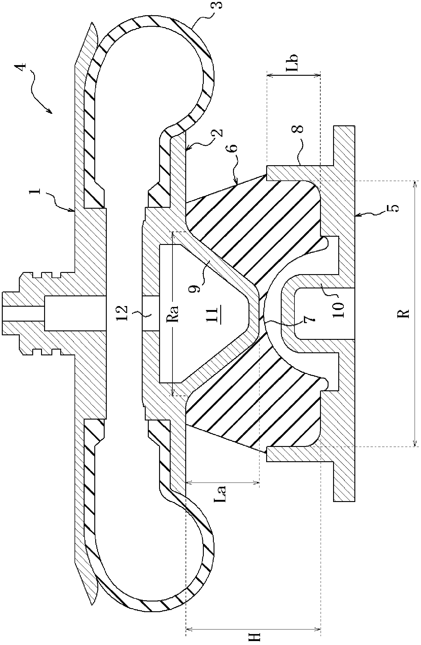
[0021] Embodiments of the present invention will be described below with reference to the drawings. figure 1 The air spring device shown in includes: an air spring 4, which has a gas-filled interior defined by an upper panel 1, a lower panel 2 and a cylindrical flexible membrane body 3, and both the upper panel 1 and the lower panel 2 may have discs shape, the cylindrical flexible membrane body 3 has, for example, an embedded reinforcement layer (not shown) inside it and airtightly connects each panel; a support plate 5, which is arranged at a distance from the lower panel 2 of the air spring 4 in this embodiment a position at a given distance; and an elastic body 6 connecting the support plate 5 and the lower panel 2 . It should be noted that although not shown in the figure, the upper panel and the support plate can be connected by elastic bodies to have the same figure 1 The air spring device is shown in an upside-down position.

[0022] The upper panel 1 and the lower ...


PUM


Abstract

An air spring device comprising: an air spring (4) formed by hermetically connecting an upper surface plate (1) and a lower surface plate (2) by a tube-shaped flexible film body (3) and having gas sealed therein; a support plate (5) disposed at a required distance from the upper surface plate (1) or the lower surface plate (2) of the air spring (4); and an elastic body (6) for connecting the support plate (5) and the upper surface plate (1) or the lower surface plate (2). A recess (7) which is recessed toward the upper surface plate (1) or the lower surface plate (2) is formed in the center region of a surface of the elastic body (6), the surface being adjacent to the support plate (5). A portion of the elastic body (6), the portion facing the support plate (5), is surrounded and restrained by an annular body (8) provided to the support plate (5). A protrusion (9) protruding to the inside of the annular body (8) is provided to the upper surface plate (1) or the lower surface plate (2).

Description

technical field [0001] The present invention relates to an air spring device, in particular for use in railway vehicles, comprising: an air spring having a filling chamber defined by an upper panel, a lower panel and a cylindrical flexible membrane airtightly connecting the panels. an interior with gas; a support plate; and an elastic body connecting one of the upper panel and the lower panel to the support plate. In particular, the present invention proposes a technology for such an air spring device that exhibits soft spring characteristics in the vertical direction to ensure high ride comfort even if the air spring leaks due to punctures, etc. A large input force in the direction reduces durability. Background technique [0002] Due to the relatively long distance between railway yards, for example, railway vehicles used in Europe, especially railway vehicles used for high-speed railways, even if the air spring of the air spring device used between the car body and the b...

Claims


Application Information

Patent Timeline
IPC IPC(8): F16F9/05F16F1/36F16F15/023F16F15/04
CPCB61F5/10F16F9/04F16F13/002F16F1/36F16F9/05F16F15/023F16F15/04
Inventor 川田昌义本村博昭
Owner BRIDGESTONE CORP
Why Eureka
Try Eureka