
Active suspension control method and system

A technology of active suspension and control method, applied in suspension, elastic suspension, transportation and packaging, etc., can solve problems such as inability to adapt, reduce vehicle ride comfort, limited suspension damping adjustment, etc., to improve ride comfort , Good vehicle ride comfort, the effect of ensuring ride comfort

Pending Publication Date: 2020-03-24
北京理工大学重庆创新中心 +1
View PDF0 Cites 6 Cited by
  • Summary
  • Abstract
  • Description
  • Claims
  • Application Information

AI Technical Summary

Problems solved by technology

[0003] When the vehicle encounters complex bumpy and undulating roads during driving, the passability of the existing active suspension and the adaptability to the complex road environment will have certain defects
Since the damping adjustment of the suspension is limited, it cannot be adapted to the situation of special unevenness on the road surface
At the same time, the controller adjustment is only when the vehicle is driving through a complex road surface, the controller continuously adjusts the active control force of the suspension according to the road surface excitation, but it takes a certain time for the general controller to adjust the suspension force, and the suspension communicates with the controller in real time. There is a time difference in the adjustment, and there is a problem of adjustment lag, which leads to the inaccurate adjustment of the active suspension under complex working conditions, and even more severe and frequent bumps, which greatly reduces the ride comfort of the vehicle

Method used


Image

  • Active suspension control method and system
  • Active suspension control method and system
  • Active suspension control method and system

Examples


Embodiment 1

[0036] Embodiment 1, see attached figure 1 , 2 , an active suspension control method, comprising the following steps:

[0037] A. Real-time observation of the road at S meters ahead to obtain the unevenness curve of the road, and estimate the posture that the vehicle should maintain when it reaches the road at S meters, to obtain the expected value of the body posture; the expected value of the body posture specifically includes: expected body pitch angle Expected body roll angle and the desired vehicle height For the convenience of observation, while obtaining the roughness curve of the road, it can also establish the three-dimensional surface of the road ahead.

[0038] B. According to the current body posture, calculate the vehicle body posture compensation value when the vehicle arrives at the road surface at S meters at the moment; combine the current body posture and the vehicle body posture compensation value at this moment to obtain the suspension posture command...

Embodiment 2

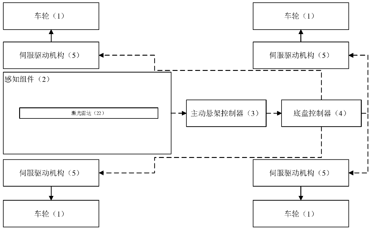
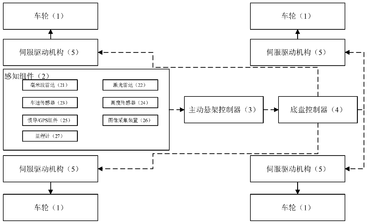
[0044] Embodiment 2, see attached Figure 4 , an active suspension control system, which includes: a perception component 2 installed in a vehicle, an active suspension controller 3 and a chassis controller 4 .

[0045] The sensing component 2 establishes a signal connection with the active suspension controller 3 , and the active suspension controller 3 establishes a signal connection with the chassis controller 4 .

[0046] The sensing component 2 is used to obtain vehicle speed, attitude, and road environment information; the sensing component 2 in this example uses a laser radar 22 .

[0047] The active suspension controller 3 acquires information according to the sensing component 2, and sends suspension posture instructions to the chassis controller 4.

[0048] One end of the suspension 9 is movably connected with the vehicle frame to form a dynamically changing suspension connection point, and the other end is connected to the wheel 1 .

[0049] The chassis controller...

Embodiment 3

[0051] Embodiment 3, see attached Figure 5 On the basis of Embodiment 2, further, the perception component 2 may further include: any one or any combination of millimeter wave radar 21 , vehicle speed sensor 23 , height sensor 24 and inertial navigation / GPS component 25 .

[0052] Among them, the millimeter-wave radar 21 can be fused with the laser radar 22 to obtain road environment information; the vehicle speed sensor 23 can be used to detect the driving speed of the vehicle; the height sensor 24 can be used to detect the height of the vehicle chassis from the ground; inertial navigation / GPS The component 25 can be used to detect the pitch direction and the roll direction of the vehicle.

[0053] Further, the sensing component 2 may further include: an image acquisition device 26; the image acquisition device 26 is used to acquire the image of the vehicle 1 traveling on the road, combined with the millimeter-wave radar 21 and the laser radar 22, a three-dimensional model o...


PUM


Abstract

The invention relates to the technical field of vehicle suspensions, and discloses an active suspension control method. In the running process of the vehicle, a front road is observed to obtain an unevenness curve of the road, and the posture of the vehicle which needs to be kept is estimated when the vehicle runs to the road surface and has smoothness, so as to obtain an expected value of the posture of the vehicle body; the active suspension controller calculates compensation information according to the road surface unevenness curved surface and obtains a suspension attitude instruction through calculation in combination with the current vehicle attitude state; when the vehicle runs to the uneven road surface, the active suspension controller sends a suspension attitude instruction to the chassis controller; the chassis controller controls the actuating mechanisms of the suspensions to independently adjust the corresponding suspensions, so that the vehicle can adapt to the fluctuation change of the road surface, the good smoothness of the whole vehicle is kept, and the riding comfort of the vehicle is improved. Meanwhile, the invention further discloses an active suspension control system.

Description

technical field [0001] The invention relates to the technical field of vehicle suspension, in particular to an active suspension control method and system. Background technique [0002] The active suspension can adjust the parameters such as stiffness and damping of the suspension according to the closed-loop control of the driving conditions of the car, so that the suspension system is always in the best vibration reduction state to ensure the smooth and smooth driving of the car. Most of the existing active suspensions generally use the LQG controller designed by the linear quadratic optimal control theory as the adjustment basis for the suspension stiffness, damping or active control force, and the selection of the weight coefficients of each performance index of the suspension will also affect the handling Stability and smoothness. [0003] When the vehicle encounters complex bumpy and undulating roads during driving, the passability of the existing active suspension an...

Claims


Application Information

Patent Timeline
IPC IPC(8): B60G17/015B60G17/0165B60G17/019B60G17/06
CPCB60G17/015B60G17/0165B60G17/019B60G17/06
Inventor 徐彬项昌乐樊伟杨海洋艾田付刘春桃
Owner 北京理工大学重庆创新中心
Learn More