
Optical fiber, optical transmission path, and optical fiber manufacturing method

A manufacturing method and optical transmission technology, applied in clad optical fiber, multi-layer core/clad optical fiber, graded index core/clad optical fiber, etc., can solve problems such as ambiguity, and achieve the goal of reducing mode dispersion Effect

Active Publication Date: 2013-07-03
FUJIKURA LTD +1
View PDF7 Cites 0 Cited by
  • Summary
  • Abstract
  • Description
  • Claims
  • Application Information

AI Technical Summary

Problems solved by technology

However, it is not clear what values ​​should be set for various parameters defining the structure of the dual-mode fiber in order to cut off the tertiary mode and minimize the modal dispersion, and a dual-mode fiber capable of long-distance transmission has not yet been realized.

Method used


Image

  • Optical fiber, optical transmission path, and optical fiber manufacturing method
  • Optical fiber, optical transmission path, and optical fiber manufacturing method
  • Optical fiber, optical transmission path, and optical fiber manufacturing method

Examples


Embodiment Construction

[0035] 〔Structure of optical fiber〕

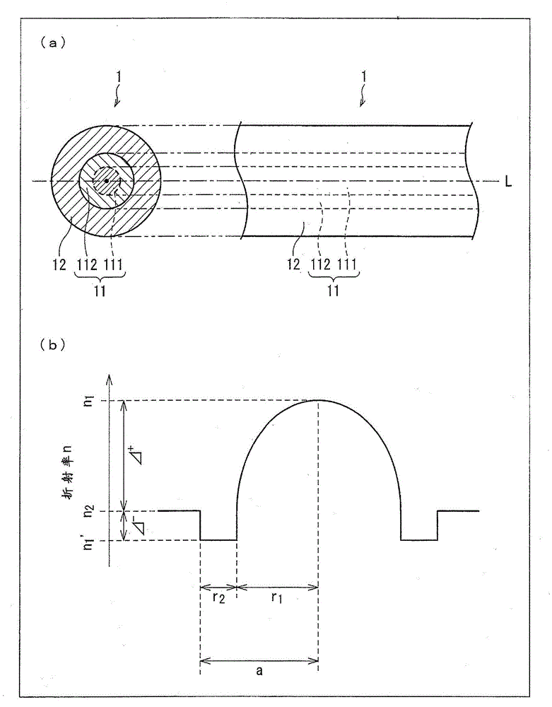
[0036] refer to figure 1 The structure of the optical fiber 1 of this embodiment will be described. figure 1 (a) is a side view and a cross-sectional view of the optical fiber 1, figure 1 (b) is a graph showing the refractive index distribution of the optical fiber 1 . also, figure 1 (b) The refractive index profile shown is at figure 1 In the optical fiber 1 shown in (a), with the central axis L (refer to figure 1 (a)) Refractive index profile on orthogonal straight lines.

[0037] Such as figure 1 As shown in (a), the optical fiber 1 is a cylindrical structure mainly composed of silica glass. a, cladding 12 with a cross-section shaped like the outer circumference radius b). According to the difference in refractive index distribution, the core 11 is further divided into an inner core 111 having a disk (radius r1)-shaped cross section, and an annular ring (inner radius r1, outer radius r1+r2) surrounding the inner core 111. The c...


PUM


Abstract

An optical fiber (1) comprises an inner core (111) with a refraction distribution which is an alpha-power distribution; an outer core (112) which surrounds the inner core (111); and a cladding (12) which surrounds the outer core (112). With the ratio of the refraction difference between the outer core (112) and the cladding (12) to the refraction difference between the center of the inner core (111) and the cladding (12) defined as Rd, and Rd set to 0.15 or more, it is possible to implement a two-mode optical fiber in which mode dispersion is minimized.

Description

technical field [0001] The present invention relates to dual mode optical fibers. It also relates to an optical transmission line comprising such an optical fiber. In addition, it also relates to a method of manufacturing such an optical fiber. Background technique [0002] In optical information communication, along with the increase in communication volume, the required transmission capacity of optical fiber as a transmission medium is also increasing. In particular, such a requirement is particularly prominent in optical fibers for long-distance transmission based on the WDM (Wavelength Division Multiplexing) method. It is expected that the increase in communication volume will continue to be explored in the future, and the increase in transmission capacity has become an urgent issue for optical fibers. [0003] In order to increase the transmission capacity of an optical fiber, it is necessary to increase the power of signal light input to the optical fiber. However,...

Claims


Application Information

Patent Timeline
Patent Type & Authority Applications(China)
IPC IPC(8): G02B6/036G02B6/028
CPCG02B6/02019G02B6/03627G02B6/02
Inventor 丸山辽桑木伸夫松尾昌一郎大桥正治
Owner FUJIKURA LTD
Learn More