Photodiode with fiber mode dispersion compensation

a fiber mode and photodiode technology, applied in the field of fabrication of photodiodes, can solve the problems of intersymbol interference, reduce the maximum data transmission rate, reduce the total transmission capacity of fiber, etc., and achieve the effect of reducing the effect of modal dispersion, less responsiveness, and reducing the respons

Active Publication Date: 2009-12-29
II VI DELAWARE INC
View PDF1 Cites 0 Cited by
  • Summary
  • Abstract
  • Description
  • Claims
  • Application Information

AI Technical Summary

Benefits of technology

[0014]The present invention can also be embodied as a method that, in one embodiment, includes the following steps: forming an n-type layer on the semiconductor substrate, forming an intrinsic layer on the n-type layer, forming a p-type layer on the intrinsic layer, and rendering the photodiode less responsive to incident light on the central region than to incident light on the peripheral region. The photodiode detects different portions of a plurality of optical signals radiating from an end of a multi-mode fiber. The effect of the central region is to reduce the effects of modal dispersion among the plurality of optical signals by selectively reducing the response to particular mode groups of the fiber.
[0015]Embodiments of the invention may also be described in terms of method for receiving and processing optical signals. For example, one embodiment includes a method for receiving information through a multimode fiber. The method includes receiving an optical signal having higher order mode groups and lower order mode groups from the multimode fiber onto a surface having a central region and a peripheral region. The lower order mode groups are incident on the central region. The higher order mode groups have portions that are incident on the peripheral region. The method further includes generating an output electrical signal in response to incident light on the peripheral region. The method includes being less responsive to incident light on the central region than to incident light on the peripheral region. Advantageously, this embodiment allows for modal dispersion to be reduced by implementing a system that effectively subtracts the lower order mode groups from the received optical signal.

Problems solved by technology

Modal dispersion reduces the maximum data transmission rate of the optical communication system and thus diminishes the total transmission capacity of the fiber.
Adjacent pulses may spread into each other causing intersymbol interference.
Importantly, the bandwidth-distance products of typical multimode fiber are severely limiting.
However, manufacturing variances and defects such as uncontrolled changes in grading profiles, a so called “alpha change”, or index peaking or dipping in the center, lead to variances in the fiber modal bandwidth.
Furthermore, as compared to single mode fibers, these limits reduce the capacity of multimode fiber by orders of magnitude.
The different propagation velocities of the distinct optical mode groups can lead to large differential mode delay (DMD) in multimode fibers.
However, this has the disadvantage of requiring complex fabrication technology, and external subtraction circuits to operate effectively.

Method used


Image

  • Photodiode with fiber mode dispersion compensation
  • Photodiode with fiber mode dispersion compensation
  • Photodiode with fiber mode dispersion compensation

Examples


Embodiment Construction

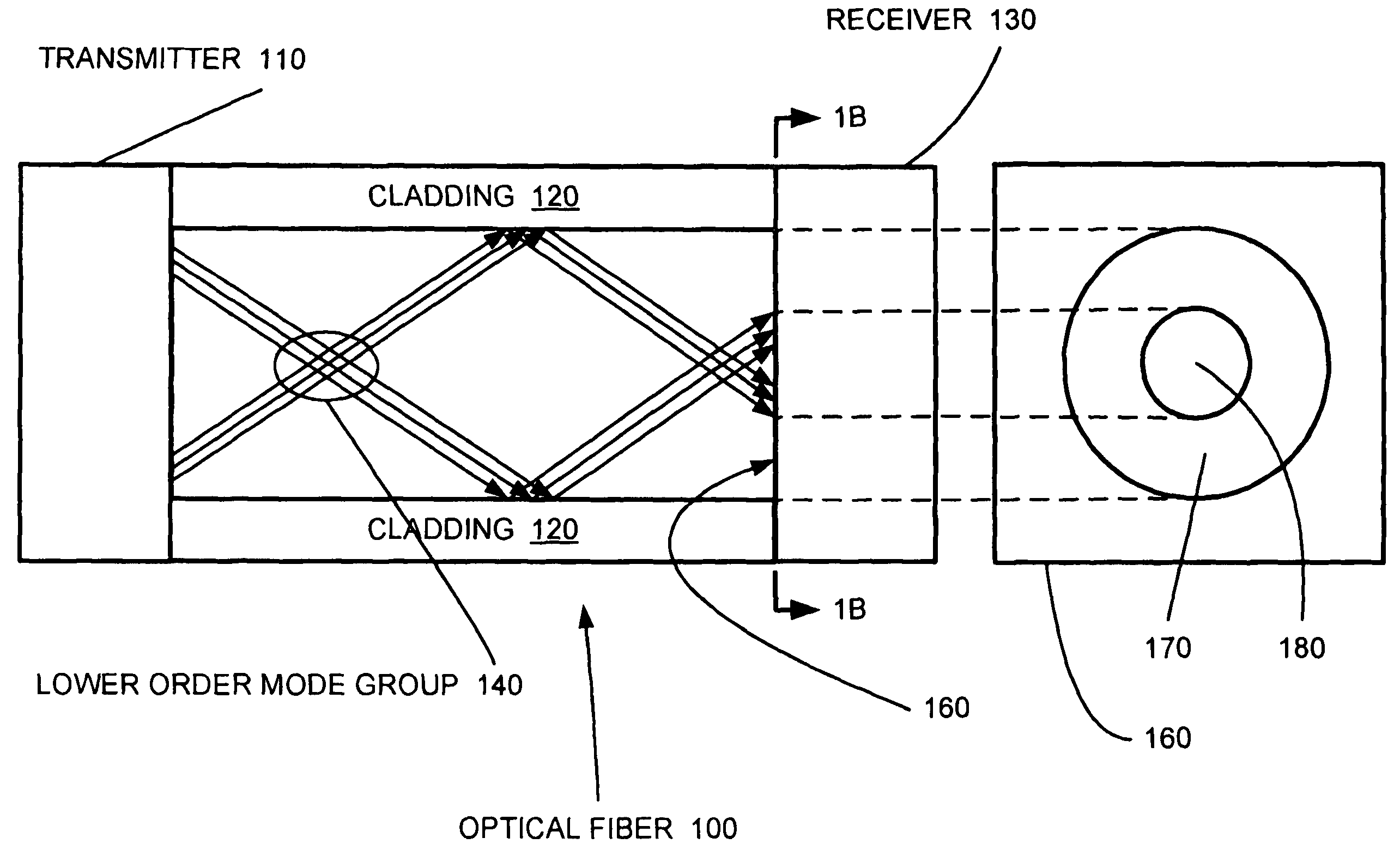
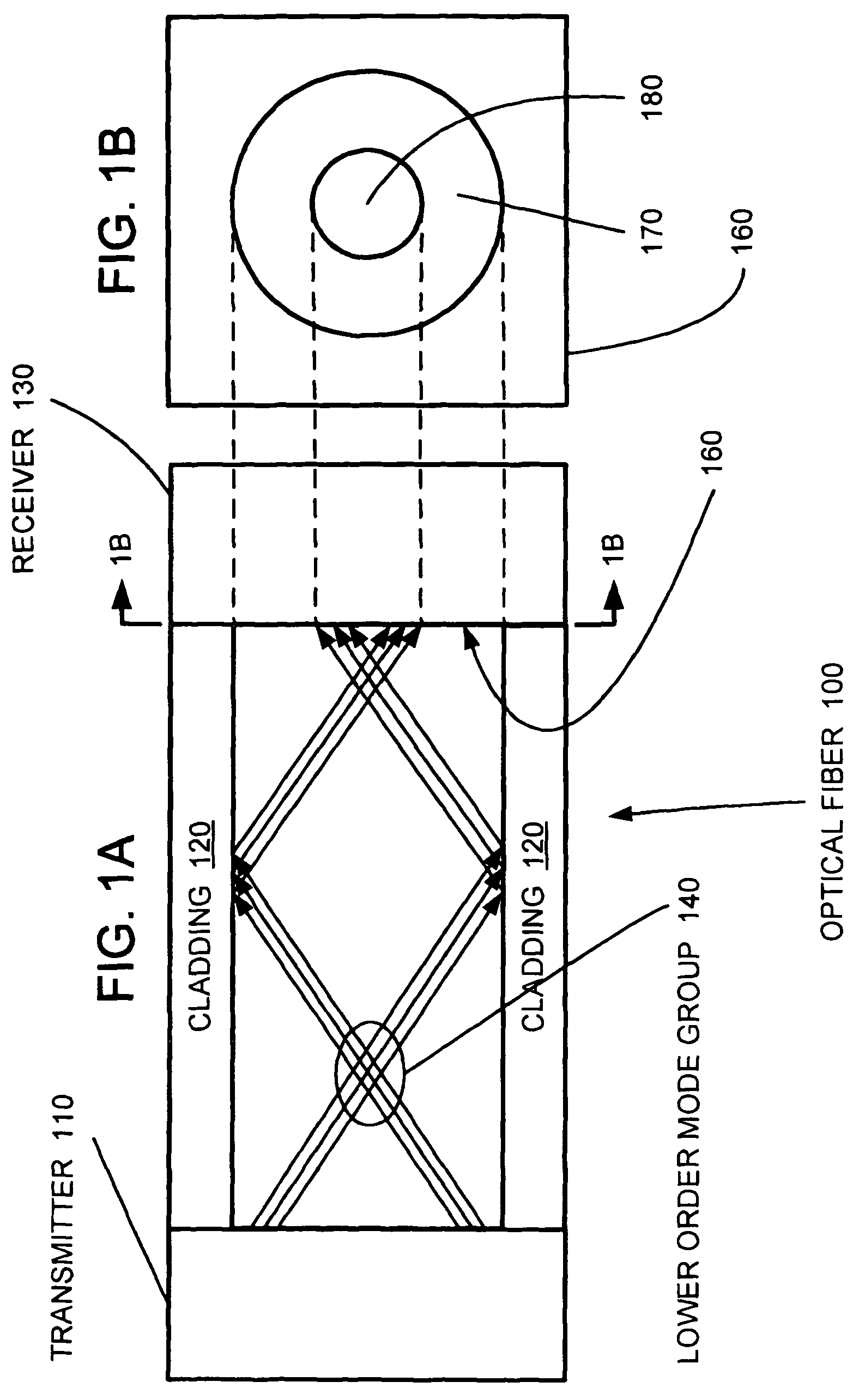
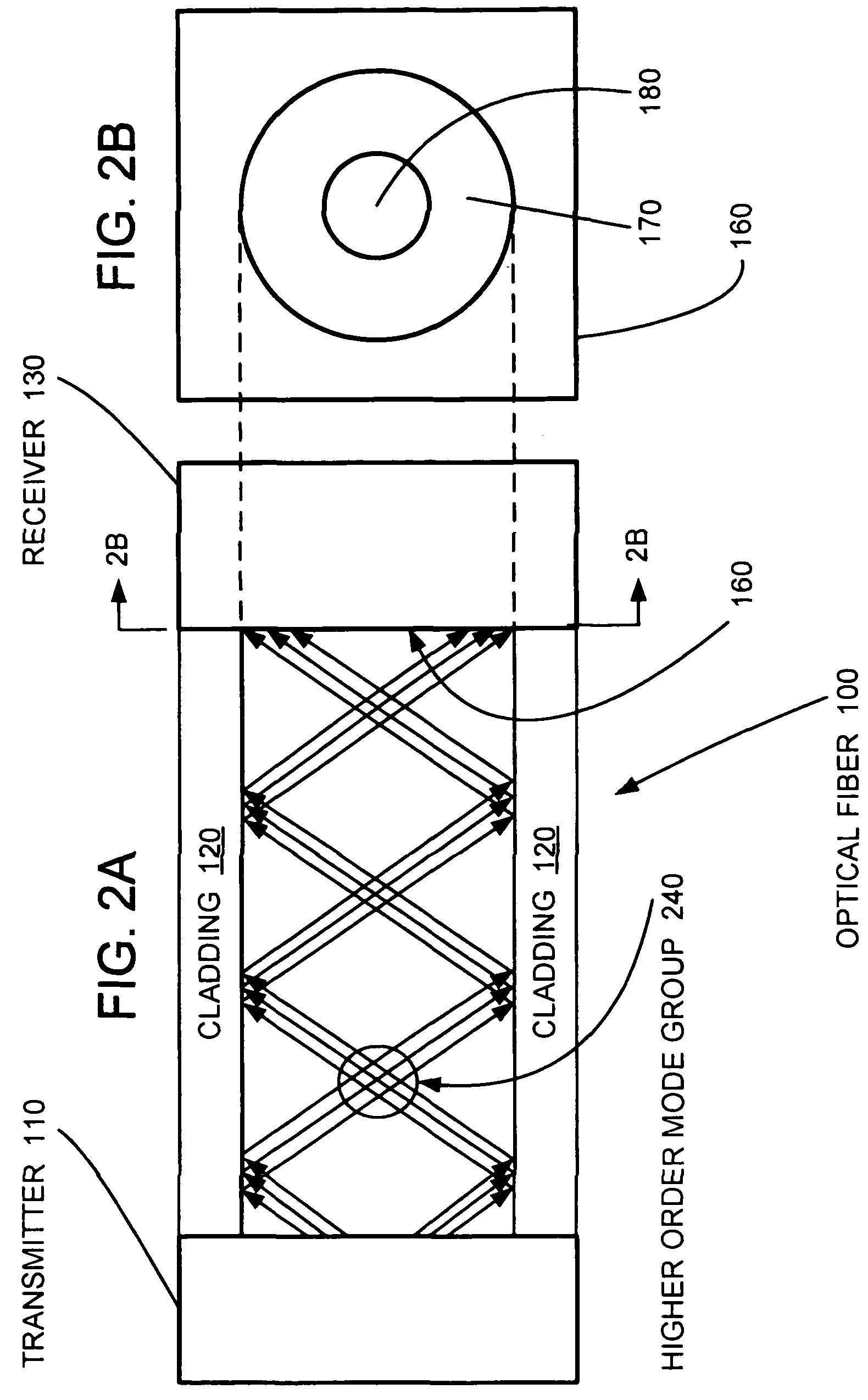
[0025]In an optical communication systems, modal dispersion limits both the bandwidth and the travel distance of the communications system. An optical signal from a laser is launched into a fiber and propagates along the fiber as multiple modes, each of which travels a different path through the fiber. The different mode velocities cause a pulse formed from more than one mode to spread out as it propagates. Each of the modes can have different arrival times at the end of the fiber, resulting in modal dispersion.

[0026]Modal dispersion causes each digital pulse of the optical signal launched through a fiber to spread as a function of the length of the fiber. Uncompensated modal dispersion limits the transmission bit rate of a digital communications system because the resultant distortion of the received signal causes high bit rate pulses to merge causing intersymbol interference. Pulses that overlap cannot be reliably distinguished.

[0027]Embodiments illustrated herein include photodio...


PUM


Abstract

A photodiode and a method of fabricating a photodiode for reducing modal dispersion and increasing travel distance. The central region of the photodiode is made less responsive to incident light than a peripheral region of the photodiode. The less responsive central region discriminates the lower order modes such that only the higher order modes are incident on the more responsive peripheral region. Because the lower order modes are subtracted, the range of propagation constants is reduced and modal dispersion is also reduced.

Description

CROSS-REFERENCE TO RELATED APPLICATIONS[0001]This application claims the benefit of U.S. Provisional Application No. 60 / 653,747, titled Photodiode with Fiber Mode Dispersion Compensation filed Feb. 16, 2005, which is incorporated herein by reference.BACKGROUND OF THE INVENTION[0002]1. The Field of the Invention[0003]The present invention relates in general to the fabrication of a photodiode to achieve fiber modal compensation in optical fiber systems.[0004]2. Description of the Related Art[0005]In an optical communication system that includes a multi-mode fiber (MMF), an optical signal launched into a fiber propagates along the fiber in multiple mode groups, each of which exhibits a different group velocity. Portions of the source optical signal reside in the different mode groups. Each of the mode groups can have different arrival times at the end of the fiber due to the different group velocities. The different group velocities of the mode groups cause a pulse, representing a bina...

Claims


Application Information

Patent Timeline
Patent Type & Authority Patents(United States)
IPC IPC(8): H01L21/04
CPCH01L31/03529H01L31/186H01L31/105Y02E10/50
Inventor TATUM, JIMMY A.
Owner II VI DELAWARE INC
Why Eureka
Try Eureka