Communications system employing single-mode lasers and multimode optical fibers

a communication system and laser technology, applied in semiconductor lasers, instruments, optical elements, etc., can solve the problems of signal or modal dispersion, limiting the use of single-mode fiber fiber optic modules, and more expensive fiber optic modules for single-mode fiber manufacture, etc., to reduce the modal dispersion, stabilize the dispersion in time, and correct the effect of dispersion

Inactive Publication Date: 2006-02-23
AVAGO TECH WIRELESS IP SINGAPORE PTE
View PDF5 Cites 2 Cited by
  • Summary
  • Abstract
  • Description
  • Claims
  • Application Information

AI Technical Summary

Benefits of technology

[0010] The present invention includes an optical transmission system having a single mode laser that generates an optical signal that is carried by a multimode optical fiber to a receiver. The single mode laser has an emitting aperture from which the optical signal is routed to the input end of the multimode optical fiber. The receiver receives light from the output end of the optical fiber. The receiver includes an equalizer that corrects the received light for modal dispersion introduced by the multimode optical fiber. Light leaving the emitting aperture of the laser is introduced into the multimode optical fiber in a pattern that excites a subset of the plurality of optical transmission modes thereby reducing the modal dispersion introduced into the light signal and stabilizing the dispersion in time. The improved dispersion enables further correction of the dispersion through the utilization of equalization techniques. The light from the emitting aperture can be routed to the input end of the optical fiber by an optical element that provides a non-uniform pattern of illumination over the input end of the optical fiber.

Problems solved by technology

In principle, a transmission system that utilizes single-mode fibers that are driven by single mode lasers has the least dispersion; however, single mode fibers present additional problems that discourage such uses, especially for low-cost applications
Single-mode fibers provide an inherently less dispersive transmission path; however, such fibers present other problems.
However, it is more expensive to manufacture fiber optic modules for single-mode fibers due, at least in part, to the tighter alignment requirements between the light source and the optical fiber.
However, when light rays from multimode or single-mode lasers are directly coupled into a MMF, the light rays travel through multiple path lengths (zigzag with varying numbers of bounces from the walls of the fiber) through the MMF, causing signal or modal dispersion.
This modal dispersion has limited the transmission distance of a multimode fiber compared to a single-mode fiber.
The distortion introduced by modal dispersion changes rapidly with time, and hence, MMFs have not been good candidates for equalization techniques.
Small changes in the coupling conditions can result in very large changes in the specific modes that are excited, and these changes can take place at rates that approach the bit rate of the transmission link.

Method used


Image

  • Communications system employing single-mode lasers and multimode optical fibers
  • Communications system employing single-mode lasers and multimode optical fibers
  • Communications system employing single-mode lasers and multimode optical fibers

Examples


Embodiment Construction

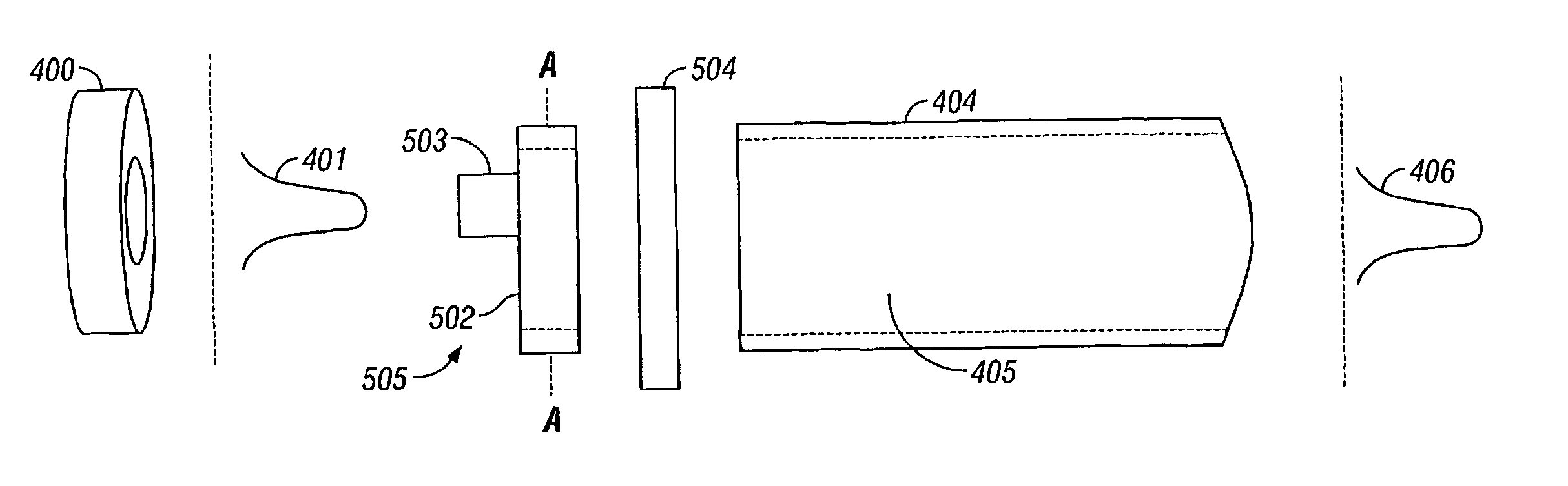
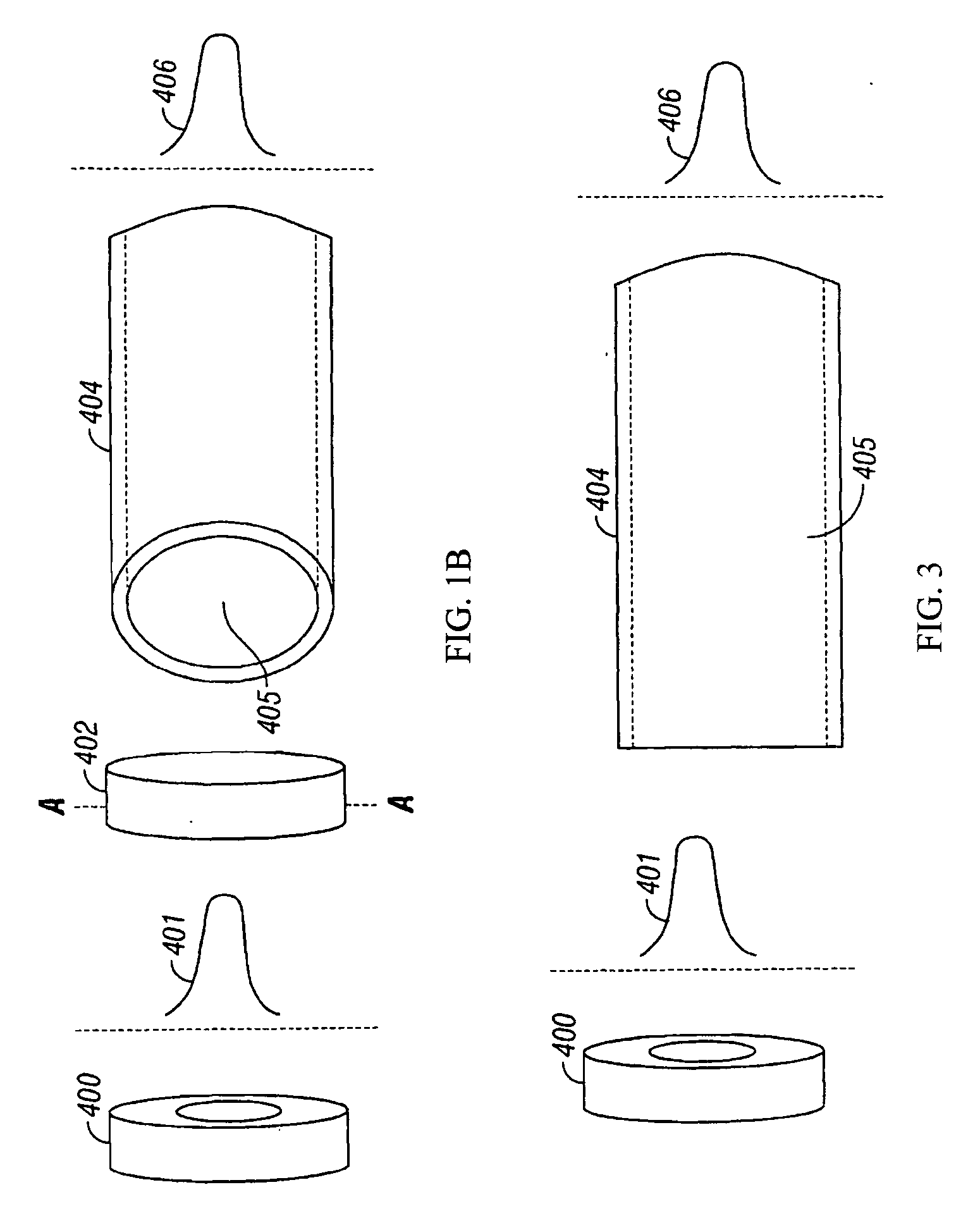
[0016] The present invention is based on the observation that even with a MMF, a light signal can be launched into the MMF in a manner that limits the number of modes that are excited in the MMF. This restricted set of modes is more stable in time, and hence, the dispersion characteristics of the MMF over time are also substantially more stable than the dispersion characteristics obtained with a conventional launch of a single-mode light signal into a MMF. This increase in stability makes adaptive dispersion correction possible, and hence, provides a means for implementing a long distance MMF connection that makes use of the large installed base of MMF channels.

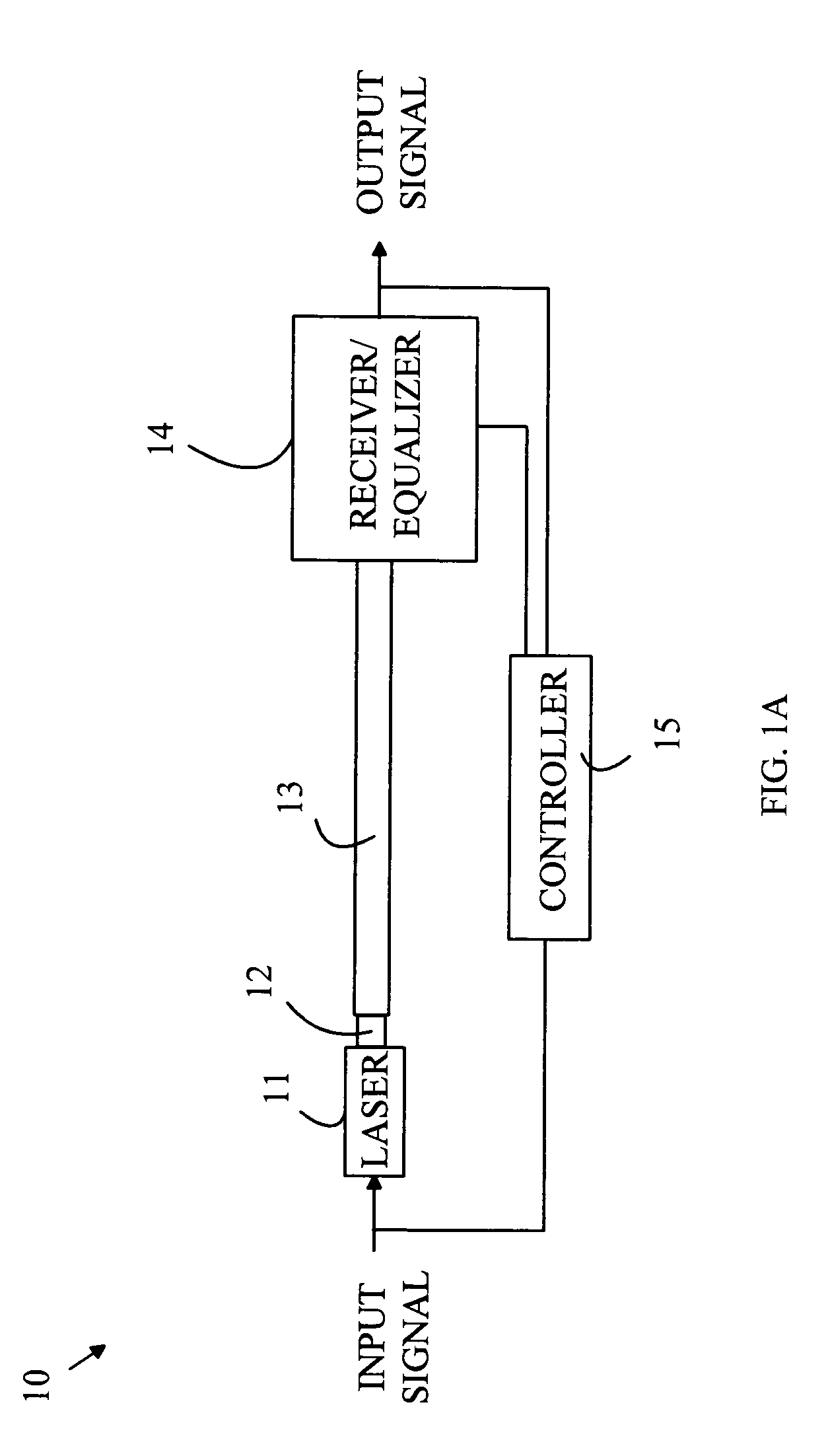
[0017] The manner in which the present invention provides its advantages can be more easily understood with reference to FIG. 1A, which is a block diagram of an optical communication system 10 according to one embodiment of the present invention. Communication system 10 converts an input signal to a light signal via a laser ...


PUM


Abstract

An optical transmission system having a single mode laser that generates an optical signal that is carried by a multimode optical fiber to a receiver is disclosed. The single mode laser has an emitting aperture from which the optical signal is routed to the input end of the multimode optical fiber. The receiver receives light from the output end of the optical fiber. The receiver includes an equalizer that corrects the received light for modal dispersion introduced by the multimode optical fiber. Light leaving the emitting aperture of the laser is introduced into the multimode optical fiber in a pattern that excites a subset of the plurality of optical transmission modes thereby reducing the modal dispersion introduced into the light signal and stabilizing the dispersion in time. The improved dispersion enables further correction of the dispersion through the utilization of equalization techniques.

Description

RELATED APPLICATION [0001] This application is a continuation-in-part of U.S. patent application Ser. No. 10 / 394,840 filed Mar. 21, 2003, which is hereby incorporated by reference.BACKGROUND OF THE INVENTION [0002] The transmission of electronic signals by converting the signals to optical signals that are transmitted via optical fibers has significant advantages over using metallic conductors to transmit the electronic signals. Optical fibers have higher bandwidth, and hence, can carry more data per unit time. In addition, optical fibers have reduced noise and are less expensive than copper conductors. [0003] Signals are transmitted on optical fibers by first converting the electrical signals to an optical signal using a light converter such as a laser or an LED. The optical signal is then coupled into the optical fiber transmission line that may include a number of amplification stations. At the receiving end of the optical fiber, the optical signal is converted back into an elect...

Claims


Application Information

Patent Timeline
Patent Type & Authority Applications(United States)
IPC IPC(8): G02B6/42G02B6/34H01S5/00H01S5/062H01S5/183H04B10/155H04B10/18H04B10/2581
CPCH01S5/005H01S5/0057H01S5/06216H04B10/503H01S2301/166H04B10/2543H04B10/2581H01S5/183
Inventor WINDOVER, LISA A.
Owner AVAGO TECH WIRELESS IP SINGAPORE PTE
Why Eureka
Try Eureka