Motor controlling device

A technology of motor control and motor, which is applied in the direction of program control, control system, digital control, etc., and can solve problems such as difficult and stable control and low rigidity

Active Publication Date: 2013-07-03
MITSUBISHI ELECTRIC CORP
View PDF6 Cites 2 Cited by
  • Summary
  • Abstract
  • Description
  • Claims
  • Application Information

AI Technical Summary

Problems solved by technology

[0004] On the other hand, if the above-mentioned low-pass filter is used, there is a problem that it is difficult

Method used


Image

  • Motor controlling device
  • Motor controlling device
  • Motor controlling device

Examples


Example Embodiment

[0026] Embodiment 1.

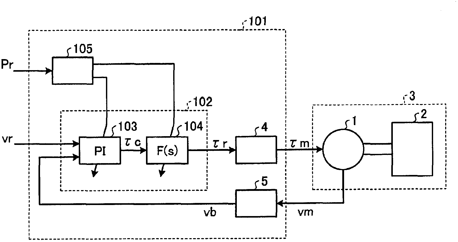
[0027] figure 1 It is a block diagram showing the overall configuration of the motor control device according to Embodiment 1 of the present invention. The motor control device 101 is set based on the speed command vr which is an operation command input from the outside, the operation (speed) vm of the motor 1 detected by using a motion detector such as an encoder (not shown), and an input from the outside The response parameter Pr of the motor 1 causes the motor 1 to generate torque (driving force) τm in such a way that the operation of the motor 1 follows the operation command. In addition, the motor 1 drives a mechanical system 3 composed of the motor 1 and a mechanical load 2 coupled with the motor 1 by generating a torque τm. In addition, the motor 1 will be referred to as a rotary type motor and the term of a rotary system such as torque will be used. However, the motor 1 is not particularly limited to a rotary type, and may be a linear motor that ge...

Example Embodiment

[0096] Implementation mode 2.

[0097] In the first embodiment, the feedback filter 104 is configured to be twice, but even if it is more simply set to once, it is possible to realize a motor control device that obtains a similar effect. Image 6 It is a configuration diagram of the motor control device of the second embodiment. In addition, the configuration of the motor control device 201 of the second embodiment is the same as that of the first embodiment except for the control constant setting unit 205 and the control calculation unit 202. The same reference numerals are attached to the same components as those in the first embodiment, and the description thereof will be omitted.

[0098] The control calculation unit 202 includes an amplification compensation unit 103 and a feedback filter 204. The feedback filter 204 is a configuration in which the secondary feedback filter 104 in the first embodiment is changed to a primary filter. Regarding the control constant setting uni...

Example Embodiment

[0123] Implementation mode 3.

[0124] Picture 9 It is a block diagram showing the structure of a motor control device according to Embodiment 3 of the present invention. The configuration of the motor control device 301 according to the third embodiment is the same as that of the first embodiment except for the control constant setting unit 305 and the control calculation unit 302. The same reference numerals are attached to the same components as those in the first embodiment, and the description thereof will be omitted.

[0125] In the first embodiment, the feedback filter 104 in the control arithmetic unit 102 outputs the torque command τr with the output of the amplifying and compensating unit 103 as an input. In contrast, in the third embodiment, the feedback filter in the control arithmetic unit 302 The detector 304 takes the detection speed vb as an input, and outputs the filter speed vbf as an intermediate variable in the control calculation unit 302.

[0126] The control...


PUM


Abstract

In order to realize as high speed and highly precise control as possible against mechanical systems with many characteristics, a motor controlling device has a filter characteristic in which, a frequency response gain is approximately 1 when a frequency is equal to or less than a filter cutoff frequency, the frequency response gain is lowered with the increase of the frequency between a filter cutoff frequency (omega fL) and a filter upper limit frequency (omega fH) that is larger than the filter cutoff frequency (omega fL), and the frequency response gain is almost constant when the frequency is equal to or more than the filter upper limit frequency (omega fH). The motor controlling device includes a feedback filter that performs calculation to cause the filter characteristic to act on a feedback transmission function. A control constant setting unit sets a speed gain (Kv) and at least one of the filter cutoff frequency (omega fL) and the filter upper limit frequency (omega fH) so that a ratio of the filter upper limit frequency (omega fH) to the filter cutoff frequency (omega fL) becomes small with respect to the increase of the speed gain (Kv).

Description

technical field [0001] The present invention relates to a motor control device for controlling the speed and position of a motor. Background technique [0002] In the motor control device that controls the speed and position of the motor, speed PI (proportional integral) control and control using a filter to form a feedback loop are generally performed, but it needs to be set according to the characteristics of the mechanical system to be driven. Control constants for determining their characteristics are desired to be set and adjusted as easily as possible to realize high-speed and high-precision control. [0003] In response to such a demand, for example, Patent Document 1 discloses a technique related to a motor control device including a speed control unit that performs PI control, and a torque filter that generally uses a low-pass filter widely. Various control constants for setting the characteristics of these respective parts are set by specific relational expression...

Claims


Application Information

Patent Timeline
IPC IPC(8): H02P29/00
CPCG05B11/42G05B2219/41152G05B19/19Y10S388/91Y10S388/902G05B6/02
Inventor 池田英俊关口裕幸五十岚裕司佐野修也磯田隆司
Owner MITSUBISHI ELECTRIC CORP
Why Eureka
Try Eureka