motor control unit
A motor control, motor technology, applied in the direction of program control, control system, digital control, etc., can solve the problems of low rigidity, difficult to stabilize control, etc.
- Summary
- Abstract
- Description
- Claims
- Application Information
AI Technical Summary
Problems solved by technology
Method used
Image
Examples
Embodiment approach 1
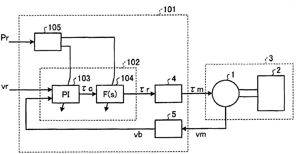
[0027] figure 1 It is a block diagram showing the overall configuration of the motor control device according to Embodiment 1 of the present invention. The motor control device 101 sets the speed command vr as a motion command input from the outside, the motion (speed) vm of the motor 1 detected using a motion detector (not shown) such as an encoder, and an external input. The response parameter Pr of the motor 1 is used to make the motor 1 generate torque (driving force) τm in such a way that the motion of the motor 1 follows the motion command. In addition, the motor 1 drives the mechanical system 3 constituted by the motor 1 and the mechanical load 2 combined with the motor 1 by generating the torque τm. Hereinafter, the motor 1 is referred to as a rotary motor and a term of a rotary system such as torque is used, but the motor 1 is not particularly limited to a rotary type, and may be a linear motor that generates thrust (driving force).
[0028] The motor control device...
Embodiment approach 2
[0097] In Embodiment 1, the feedback filter 104 has a second-order configuration, but a motor control device that can achieve similar effects can be realized even if it is simpler to use a single-order configuration. Image 6 It is a block diagram of the motor control device of Embodiment 2. In addition, the configuration of the motor control device 201 of the second embodiment is the same as that of the first embodiment except for the control constant setting unit 205 and the control calculation unit 202 . The same reference numerals are assigned to the same components as those in Embodiment 1, and description thereof will be omitted.
[0098] The control calculation unit 202 includes an amplification compensation unit 103 and a feedback filter 204 . The feedback filter 204 is configured by changing the secondary feedback filter 104 in the first embodiment to a primary filter. The control constant setting unit 205 is different from the control constant setting unit 105 in t...
Embodiment approach 3
[0124] Figure 9 It is a block diagram showing the configuration of a motor control device according to Embodiment 3 of the present invention. In addition, the configuration of the motor control device 301 of the third embodiment is the same as that of the first embodiment except for the control constant setting unit 305 and the control calculation unit 302 . The same reference numerals are assigned to the same components as those in Embodiment 1, and description thereof will be omitted.
[0125] In Embodiment 1, the feedback filter 104 in the control calculation unit 102 outputs the torque command τr with the output of the amplification compensation unit 103 as input. In contrast, in the third embodiment, the feedback filter 104 in the control calculation unit 302 The filter 304 receives the detection speed vb as an input, and outputs the filter speed vbf as an intermediate variable in the control computing unit 302 .
[0126] The control calculation unit 302 includes an am...
PUM
 Abstract
Description
Claims
Application Information
 - R&D
- Intellectual Property
- Life Sciences
- Materials
- Tech Scout
- Unparalleled Data Quality
- Higher Quality Content
- 60% Fewer Hallucinations
Browse by: Latest US Patents, China's latest patents, Technical Efficacy Thesaurus, Application Domain, Technology Topic, Popular Technical Reports.
© 2025 PatSnap. All rights reserved.Legal|Privacy policy|Modern Slavery Act Transparency Statement|Sitemap|About US| Contact US: help@patsnap.com


