Optical detection method for plate material forming and springback

An optical detection and sheet material technology, applied in the direction of using optical devices, measuring devices, instruments, etc., can solve the problems of difficult to accurately measure the rebound amount and physical expression, and achieve the effect of reducing the handling cost.

Active Publication Date: 2013-07-10
GUANGZHOU WANBAO GRP MINQUAN ELECTRICAL APPLIANCE CO LTD
View PDF4 Cites 11 Cited by
  • Summary
  • Abstract
  • Description
  • Claims
  • Application Information

AI Technical Summary

Problems solved by technology

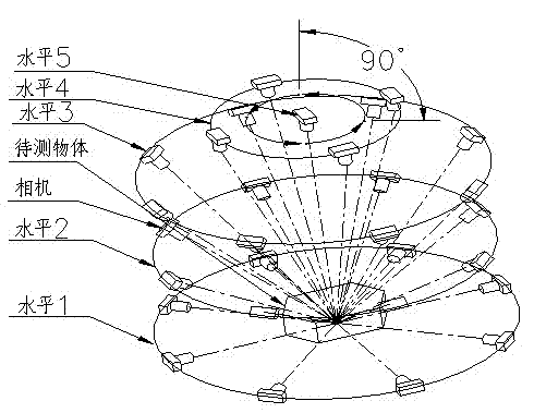
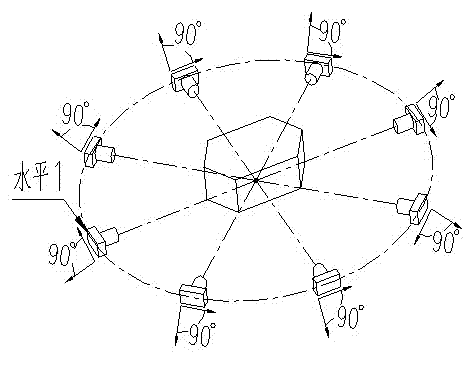
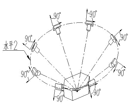
[0006] The technical solution of the present invention is: an optical detection method for the springback of sheet metal forming, which uses a method combining photogrammetry and surface scanning to detect the amount of springback of the workpiece, and the shape after springback is expressed in the form of the measured point cloud , the shape before springback is expressed by CAD digital model, and the two are compared in the reverse software, and the three-dimensional direction value of springback and the visual digital expression method are determined at any position of the workpiece, which solves the difficulty of accurately measuring the springback of large complex curved surface products and the physical To formulate the problem, its steps are as follows:

Method used


Image

  • Optical detection method for plate material forming and springback
  • Optical detection method for plate material forming and springback
  • Optical detection method for plate material forming and springback

Examples


Embodiment 1

[0056] The research object is taken from the BC-48 refrigerator door shell of a famous domestic appliance company, such as Figure 7 As shown, BC-48 is a small type refrigerator, and its door shell is made of thin plate, and the material used in production is black work, with a thickness of 0.6 mm. Spray plastic after forming to ensure the appearance. Apply the detection and evaluation method proposed in this paper to obtain the geometric shape of the refrigerator door shell, its cross-sectional shape after forming and the designed mold CAD digital model are aligned and compared, and the three-dimensional springback value of different parts and directions of the two can be obtained.

[0057] The experimental steps are as follows:

[0058] (1) Arrange coded markers, non-coded markers and scales around the workpiece to be measured;

[0059] (2) Take photos, and the photogrammetry system calculates the coded points and non-coded points on the surface of the door shell, such as ...

Embodiment 2

[0079] The measurement example is the rear floor longitudinal beam (500 mm×300 mm×100 mm) of a certain model of car. Figure 14-18The measurement procedure for the rear floor rail of a car is shown. The photogrammetry system calculates the three-dimensional coordinate matrix of all non-coded points by pasting coded and non-coded points on the surface of the workpiece and placing the Invar alloy scale. Based on the derived non-coding marker point matrix; the surface scanning system scans the geometric features of the workpiece surface to obtain a point cloud group that can represent the complete geometric information of the workpiece. After performing operations such as deletion, thinning, and denoising on overlapping surfaces, they are merged to obtain the final point cloud. The point cloud was input into the Geomagic Qualify software and set as the test object. The mathematical model of the workpiece is copied through features in Pro / E to obtain the surface shape of its out...


PUM


Abstract

The invention discloses an optical detection method for plate material forming and springback. A photographical measurement and surface scanning combined method is adopted to realize the detection for the springback amount of a workpiece;the shape after the springback is expressed by a point cloud form, and the shape before the springback is expressed by a computer aided design (CAD) numerical simulation; the later shape and the previous shape are compared through inversion software; and a springback three-dimensional direction value and a visible digital expression mode of the springback can be determined at any position of the workpiece. A photographical measurement technology and a surface scanning technology are combined for measurement, so that the problems of low point cloud processing speed and low fusion precision of the pure surface scanning technology are solved; and by using the three-dimensional optical detection method, the definite advantages on large-size, ultra-large-size, ultra-small-size and A-level curved surface products or workpieces which can not be detected by using a contact measurement method are realized.

Description

technical field [0001] The invention relates to the introduction of an optical detection method in the field of springback in sheet metal forming, specifically a process of applying photogrammetry technology and surface scanning technology to obtain the springback value of sheet metal. Background technique [0002] The inevitable rebound phenomenon of sheet metal in the stamping process is attracting more and more attention from engineers and technicians in the product manufacturing department. Especially for various shallow deep-drawing parts, the springback problem is more obvious, and the importance of solving the springback problem is also more prominent. The accuracy of springback control will seriously affect the forming quality and dimensional accuracy of the product, and it is also one of the forming defects that are difficult to effectively overcome in the actual process. Due to the complexity of the forming process itself, the solution to the springback problem ha...

Claims


Application Information

Patent Timeline
Patent Type & Authority Applications(China)
IPC IPC(8): B21C51/00B21D22/00G01B11/00
Inventor 张德海吴超王辉李艳芹白代萍陈鹿民罗国富
Owner GUANGZHOU WANBAO GRP MINQUAN ELECTRICAL APPLIANCE CO LTD
Why Eureka
Try Eureka