Rotary table with brake locking mechanism

A technology of locking mechanism and rotary table, which is applied in the field of rotary table, can solve the problems of difficult miniaturization, high equipment cost, and large space occupied by hydraulic equipment, and achieve the effect of equipment cost reduction

Active Publication Date: 2015-08-19
PRECISION MACHINERY RES & DEV CENT
View PDF6 Cites 0 Cited by
  • Summary
  • Abstract
  • Description
  • Claims
  • Application Information

AI Technical Summary

Problems solved by technology

[0004] However, if the clamp 95 is used to tighten the disc 94, a strong force is required to exert the locking effect. Therefore, the clamp 95 mostly uses hydraulic equipment as the driving source, and the hydraulic equipment has many and complicated parts, so The equipment cost remains high, and the hydraulic equipment takes up a lot of space, so it is not easy to miniaturize

Method used


Image

  • Rotary table with brake locking mechanism
  • Rotary table with brake locking mechanism
  • Rotary table with brake locking mechanism

Examples


Embodiment Construction

[0027] Please refer to Fig. 1 to Fig. 6, those shown in the figures are the selected embodiment structures of the present invention, which are for illustration purposes only, and are not limited by such structures in the patent application.

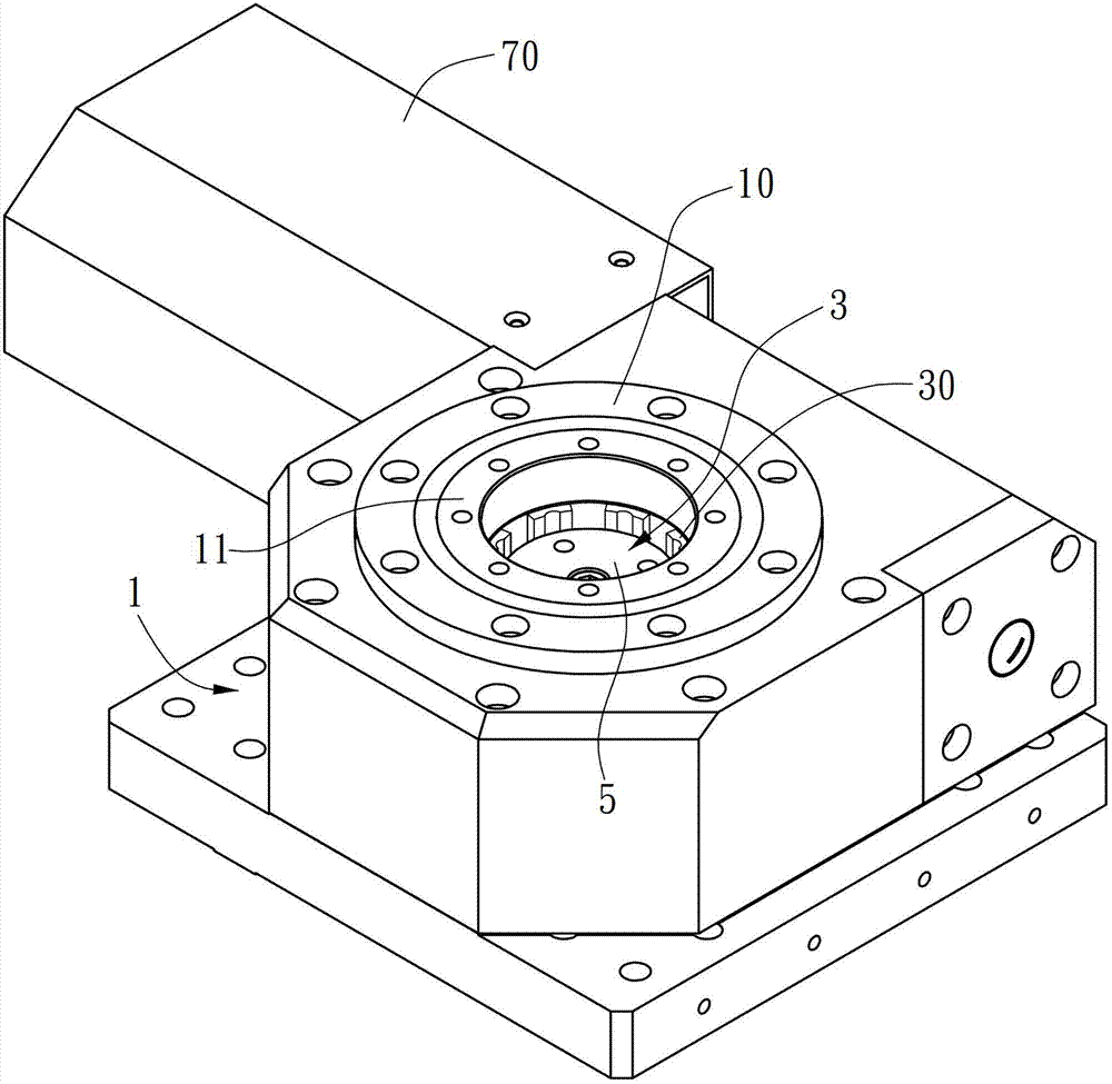
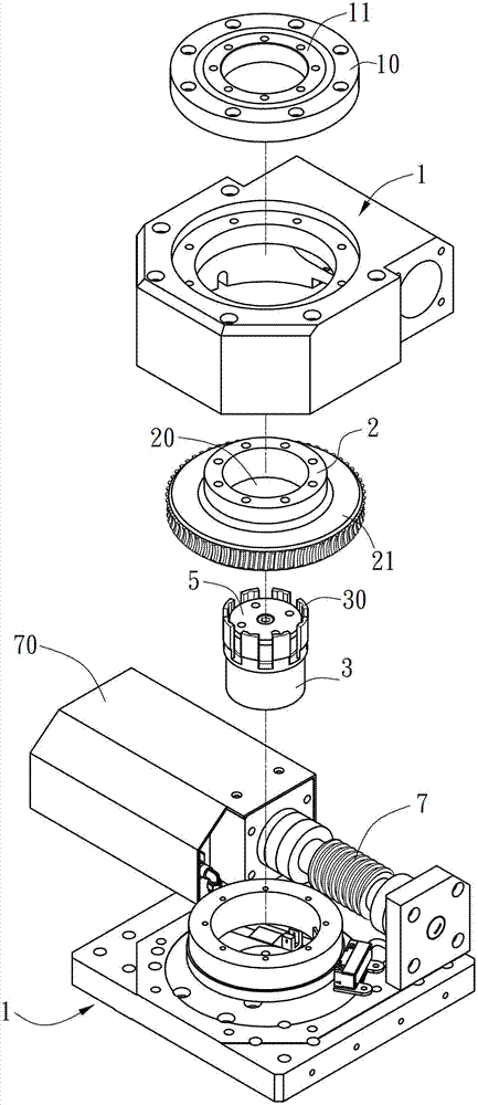
[0028] This embodiment provides a turntable with a brake locking mechanism. As shown in Figure 1, it is the structure of the turntable in this embodiment. It can be seen from Figure 2 and Figure 5 that the turntable in this embodiment is mainly in a body 1 A rotating shaft 2 is provided, and the rotating shaft 2 is driven to rotate in the body 1 by a driving member. The brake locking mechanism is set in the body 1 to brake the rotating shaft 2 .

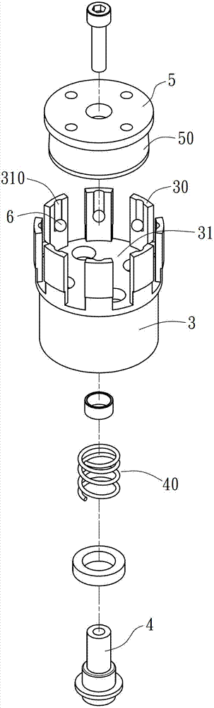
[0029] The brake locking mechanism of the present invention, as shown in Fig. 1 to Fig. 5, includes a pneumatic cylinder 3, a piston rod 4, a follower 5 and several rolling parts 6, wherein:

[0030] As shown in Figures 1 to 2, in this embodiment, a positioning plate 10 is fixed on the top of th...


PUM


Abstract

The present invention provides a rotating platform with a brake locking mechanism. The rotating platform comprises a rotating shaft and a brake locking mechanism in a body. The brake locking mechanism comprises an air cylinder, a piston rod, a driven member and a plurality of rolling members, wherein a high-pressure air source enters into a chamber of the air cylinder via the body, the piston rod is driven to drive the driven member to perform straight reciprocating motion, the rolling members are driven to slide aside because of the oblique cone shape of the driven member which is wider in the bottom than the top, and a plurality of claw portions on the top end of the air cylinder are made to expand externally to press against inner walls of the shaft holes in the center of the rotating shaft, thereby enabling the rotating shaft to have the brake locking effect. According to the rotating platform with a brake locking mechanism, only the high-pressure air source is used as a driving source, an adequate brake torque can still be obtained after the amplification of the air pressure thrust through the oblique faces, and the effects of brake locking by the rotating shaft can thus be obtained. Moreover, high-pressure air is used as the driving source and oil pressure equipment with complicated parts is not need to be configured, so the equipment is low in costs and has the advantages of miniaturization.

Description

technical field [0001] The invention relates to a rotary table of a machine tool, in particular to a rotary table with a brake locking mechanism. Background technique [0002] At present, four-axis or five-axis multi-axis machine tools are commonly seen on the market. The rotation of the rotary table is mostly driven by a direct-drive motor, or driven by a worm and a worm wheel. However, due to consideration of processing efficiency during processing, when doing When planning the path, we will try our best to focus on fixed-axis processing, and at this time, the two rotating axes will be locked by brakes to increase their processing stability. [0003] As shown in Figure 8, it is the brake locking mechanism of the existing rotary table. A rotating shaft 91 is arranged in the center of a body 90, and a worm wheel 93 is driven by a worm 92 to drive the rotating shaft 91 to rotate. The rotating shaft 91 is provided with a Disc 94, the disc 94 rotates with the rotating shaft 91...

Claims


Application Information

Patent Timeline
Patent Type & Authority Patents(China)
IPC IPC(8): B23Q1/26
Inventor 刘育安
Owner PRECISION MACHINERY RES & DEV CENT
Why Eureka
Try Eureka