Supercharge Your Innovation With Domain-Expert AI Agents!

Spiral water cooling excitation mechanism of intelligent boring bar driven by embedded giant magnetostrictive material

A giant magnetostrictive and boring bar technology, applied in piezoelectric effect/electrostrictive or magnetostrictive motors, generators/motors, metal processing machinery parts, etc., can solve the impact of machine tool spindle dynamic balance, magnetic field cycle Insufficient uniform orientation, poor cooling effect, etc., to achieve the effect of simple structure, preventing the influence of temperature, and facilitating processing and assembly

Inactive Publication Date: 2015-05-20
ZHEJIANG UNIV
View PDF7 Cites 0 Cited by
  • Summary
  • Abstract
  • Description
  • Claims
  • Application Information

AI Technical Summary

Problems solved by technology

Both of the above two patents built the excitation coil and giant magnetostrictive material into the front end of the spindle. This structure has the following defects: it needs to use high-speed brushes for contact drive and control; the excitation coil is limited by the size of the machine tool spindle, and will affect the The dynamic balance of the main shaft is affected; the coil adopts the spiral air cooling method, which can only cool the inner surface of the coil, and the cooling effect is not good; the overall structure is complex and there are too many links, which is not easy to realize
[0004] Patent No.: CN201110190705.0, Publication No.: CN102274989A Chinese patent discloses "boring bar device driven by giant magnetostrictive material". Winding multiple sets of coils, this structure has the disadvantage that the circumferential direction of the magnetic field is not uniform enough

Method used


Image

  • Spiral water cooling excitation mechanism of intelligent boring bar driven by embedded giant magnetostrictive material
  • Spiral water cooling excitation mechanism of intelligent boring bar driven by embedded giant magnetostrictive material
  • Spiral water cooling excitation mechanism of intelligent boring bar driven by embedded giant magnetostrictive material

Examples


Embodiment Construction

[0017] The present invention will be further described below in conjunction with drawings and embodiments.

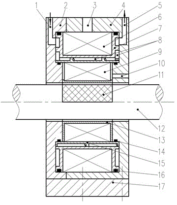
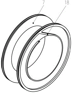
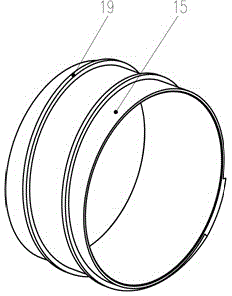
[0018] Such as Figure 1-Figure 4 As shown, the present invention includes a coil end cover 2, a coil housing 4, a large coil 6, a large coil bobbin 7, a spiral water cavity 8, a small coil 9, a giant magnetostrictive material block 11, a boring bar 12, and a small coil bobbin 13 , small sealing ring 14, sealing sleeve 15, large sealing ring 16, coil base 17, water-proof boss 18; the outer cylindrical surface of boring bar 12 is axially provided with grooves, and giant magnetostrictive material blocks are housed in the grooves 11. The small bobbin 13 is set on the shaft section of the boring bar 12 equipped with the giant magnetostrictive material block 11, the small coil 9 is wound on the small bobbin 13, and the sealing sleeve 15 with the external thread 19 is installed on the small coil Outside the frame 13, the large coil frame 7 with spiral water-proof bosses 18 o...


PUM


Abstract

The invention discloses a spiral water cooling excitation mechanism of an intelligent boring bar driven by an embedded giant magnetostrictive material. A giant magnetostrictive material block is filled in an axial groove in the outer cylindrical surface of the boring bar; a shaft section of the boring bar, which is mounted with the giant magnetostrictive material block, is sleeved with a small coil framework; a sealing sleeve provided with an outer screw thread is mounted outside the small coil framework; a large coil framework provided with a spiral water-preserved boss is mounted outside the sealing sleeve; the two end surfaces of the large coil framework and the small coil framework are respectively mounted with a coil casing and a coil end cover; a water inlet of the spiral water cavity is formed in the outer circumferential surface and a water outlet is formed in the outer circumferential surface of the coil casing. According to the invention, a spiral water cooling structure and the combined coil are adopted to generate an even magnetic field; the affect of the temperature on the giant magnetostrictive material is reduced; and non-contact driving and non-contact control are achieved. The spiral water cooling excitation mechanism of the intelligent boring bar driven by the embedded giant magnetostrictive material is applicable to non-contact large-power driving of ultra-precise complex non-circular hole processing.

Description

technical field [0001] The invention relates to an excitation coil mechanism, in particular to a spiral water-cooled excitation mechanism embedded with a giant magnetostrictive material intelligent boring bar. Background technique [0002] For hole parts that are subjected to large non-uniform stress during work, such as engine cylinder holes and piston pin holes, in modern manufacturing, in order to reduce the stress concentration of such holes, reduce fatigue damage of parts, and prolong their service life In order to improve the service life, this type of hole is specially processed into a non-cylindrical hole (special-shaped hole), which requires that in the precision boring process, the boring tool should not only have high-speed rotating motion along the machine tool spindle, but also have a cutting motion along the diameter of the hole. Feed movement, and radial feed movement requires a high frequency response to meet the needs of precision machining of different shap...

Claims


Application Information

Patent Timeline
Patent Type & Authority Patents(China)
IPC IPC(8): B23Q5/28H02N2/04
Inventor 邬义杰彭黄湖沙钊曾铭辰梁锋
Owner ZHEJIANG UNIV
Features
  • R&D
  • Intellectual Property
  • Life Sciences
  • Materials
  • Tech Scout
  • Unparalleled Data Quality
  • Higher Quality Content
  • 60% Fewer Hallucinations
Learn More