Cylindrical paper tube opposition cutting machine

A cylindrical paper and extension technology, which is applied in papermaking, paper/cardboard containers, container manufacturing machinery, etc., can solve the problems of low efficiency, scrapped cylindrical paper tubes, time-consuming and laborious, etc. simple structure

Active Publication Date: 2013-07-10
GUANGBO GRP
View PDF3 Cites 1 Cited by
  • Summary
  • Abstract
  • Description
  • Claims
  • Application Information

AI Technical Summary

Problems solved by technology

In the prior art, cutting the paper tube in half can only be cut manually with a knife, but cutting the paper tube in this way is time-consuming, laborious, inefficient, affects the roundness of the cylindrical paper tube, and even causes the circularity of the cylindrical paper tube. scrapped

Method used


Image

  • Cylindrical paper tube opposition cutting machine
  • Cylindrical paper tube opposition cutting machine
  • Cylindrical paper tube opposition cutting machine

Examples


Embodiment 1

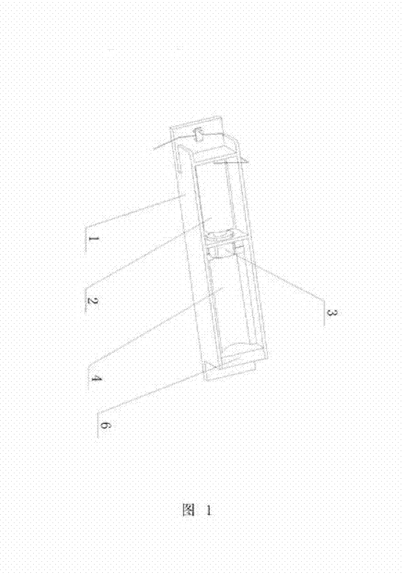
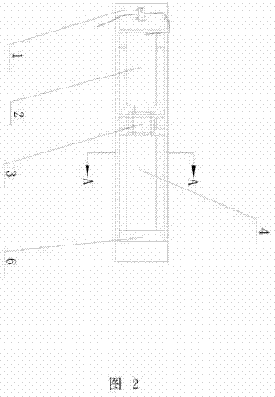
[0023] Such as Figure 1 to Figure 6 Shown, a kind of cylindrical paper tube splitting machine of the present invention is characterized in that: it comprises housing 1; The cylinder 2 that is fixed on the housing 1 and the cutting device 3 that is installed on the free end of piston rod of cylinder 2; It also comprises A cavity 4 for placing a cylindrical paper tube; the cavity 4 is provided with a guide device for the cutting device 3; the axis of the piston rod is on the same line as the axis of the cavity 4; the cavity 4 The rear end is equipped with an axial limit device for the cylindrical paper tube.

[0024] The cutting device 3 is detachably connected to the piston rod of the cylinder 2 .

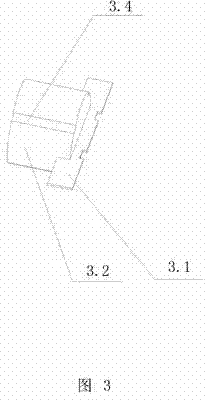
[0025] The cutting device 3 is composed of a cutting knife 3.1 and a cylinder 3.3 or cylinder 3.2 for fixing the cutting knife 3.1.

[0026] The cutting knife 3.1 is fixed on the front end of the cylinder 3.3 or the cylinder 3.2; the cutting knife 3.1 extends radially to both sid...

Embodiment 2

[0034] Such as Figure 1 to Figure 6 Shown, a kind of cylindrical paper tube splitting machine of the present invention is characterized in that: it comprises housing 1; The cylinder 2 that is fixed on the housing 1 and the cutting device 3 that is installed on the free end of piston rod of cylinder 2; It also comprises A cavity 4 for placing a cylindrical paper tube; the cavity 4 is provided with a guide device for the cutting device 3; the axis of the piston rod is on the same line as the axis of the cavity 4; the cavity 4 The rear end is equipped with an axial limit device for the cylindrical paper tube.

[0035] The cutting device 3 is detachably connected to the piston rod of the cylinder 2 .

[0036] The cutting device 3 is composed of a cutting knife 3.1 and a cylinder 3.3 or cylinder 3.2 for fixing the cutting knife 3.1.

[0037] The cutting knife 3.1 is fixed on the front end of the cylinder 3.3 or the cylinder 3.2; the cutting knife 3.1 extends radially to both sid...


PUM


Abstract

The invention discloses a cylindrical paper tube opposition cutting machine. The cylindrical paper tube opposition cutting machine is characterized by comprising a housing (1), a cylinder (2) fixed on the housing (1), a cutting device (3) mounted at the free end of a piston rod of the cylinder (2) and a cavity (4) used for disposing a cylindrical paper tube, wherein the cavity (4) is provided with a guide device of the cutting device (3), the axis of the piston rod and the axis of the cavity (4) are in a straight line, and an axial limiting device of the cylindrical paper tube is arranged at the rear end of the cavity (4). Therefore, the cylinder is started after the cylindrical paper tube is disposed in the cavity, then the piston rod of the cylinder drives the cutting device to move forward, and the cylindrical paper tube can be cut quickly, easily and efficiently.

Description

technical field [0001] The invention relates to a cutting tool, in particular to a cylinder paper tube splitting machine. Background technique [0002] At present, most wine bottles containing red wine are set in cylindrical cartons. The production of cartons is generally to cut the paper tube in half. One side of the paper tube is hinged together, and the other side is equipped with a lock. buckle mechanism. In the prior art, cutting the paper tube in half can only be cut manually with a knife, but cutting the paper tube in this way is time-consuming, laborious, inefficient, affects the roundness of the cylindrical paper tube, and even causes the circularity of the cylindrical paper tube. scrapped. Contents of the invention [0003] The technical problem to be solved by the present invention is to provide a cylindrical paper tube splitting machine with simple structure and high cutting efficiency. [0004] The technical solution of the present invention is: a cylindric...

Claims


Application Information

Patent Timeline
Patent Type & Authority Applications(China)
IPC IPC(8): B31B1/20B31B50/20
Inventor 陈国强
Owner GUANGBO GRP
Why Eureka
Try Eureka