Connection structure for safe air bag frame

A connection structure and airbag technology, which is applied in vehicle safety arrangement, pedestrian/passenger safety arrangement, vehicle components, etc., can solve the problems of airbag protection effect, instrument panel fragments splashing, secondary casualties, airbag frame easy damage, etc., to achieve Good protection effect, low cost, uniform force effect

Active Publication Date: 2015-07-08
HANGZHOU BRANCH ZHEJIANG GEELY AUTOMOBILE RES INST +2
View PDF6 Cites 2 Cited by
  • Summary
  • Abstract
  • Description
  • Claims
  • Application Information

AI Technical Summary

Problems solved by technology

[0003] The purpose of the present invention is to overcome the deficiencies of the current airbag frame structure in which the airbag frame is easily damaged when the car is in a collision accident, resulting in the failure of the airbag to deploy normally, affecting the protective effect and causing secondary casualties due to the splash of instrument panel fragments when the airbag is deployed, and to provide a In the event of a car collision, the airbag can be deployed normally. The airbag frame connection structure has a good protective effect and the dashboard fragments do not splash when the airbag is deployed.

Method used


Image

  • Connection structure for safe air bag frame
  • Connection structure for safe air bag frame
  • Connection structure for safe air bag frame

Examples


Embodiment 1

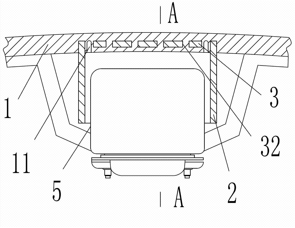
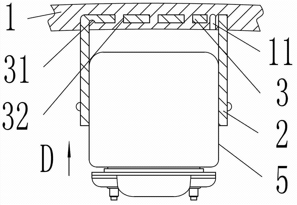
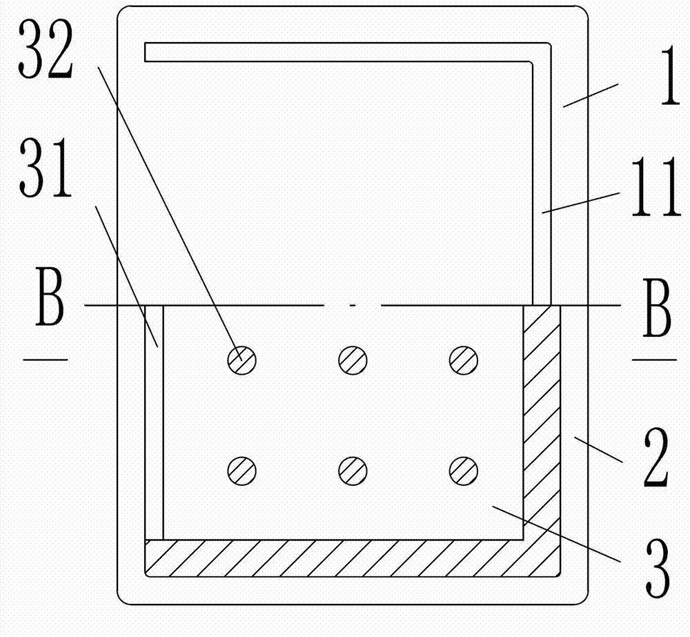
[0023] Embodiment 1, as attached figure 1 , attached figure 2 , attached image 3 , attached Figure 4 Shown: an airbag frame connection structure, including an instrument panel 1, a metal airbag frame 2 located inside the instrument panel 1, and a metal end plate 3 whose size is smaller than the inner circumference of the metal airbag frame 2.

[0024] The metal airbag frame 2 is a rectangular frame or a polygonal frame; the metal airbag frame 2 is made of steel, aluminum or copper; the metal end plate 3 is made of steel, aluminum or copper. In this embodiment, the metal airbag frame 2 is a rectangular frame; the shape of the metal end plate 3 is rectangular; the material of the metal airbag frame 2 is steel; the material of the metal end plate 3 is steel.

[0025] One end surface of the metal end plate 3 is provided with a through groove 31 along one side of the metal end plate 3; the cross-sectional shape of the through groove 31 is U-shaped; the depth of the through gr...

Embodiment 2

[0029] Embodiment 2, as attached figure 1 , attached Figure 5 , attached Image 6 , attached Figure 7 Shown: an airbag frame connection structure, including an instrument panel 1, a metal airbag frame 2 located inside the instrument panel 1, and a metal end plate 3 whose size is smaller than the inner circumference of the metal airbag frame 2.

[0030] The metal airbag frame 2 is a rectangular frame or a polygonal frame; the metal airbag frame 2 is made of steel, aluminum or copper; the metal end plate 3 is made of steel, aluminum or copper. In this embodiment, the metal airbag frame 2 is a rectangular frame; the shape of the metal end plate 3 is rectangular; the material of the metal airbag frame 2 is steel; the material of the metal end plate 3 is steel.

[0031] The metal end plate 3 is located at one end of the metal airbag frame 2, and one side of the metal end plate 3 is hinged to one side of the metal airbag frame 2 through the hinge shaft 4; one end of the metal e...


PUM


Abstract

The invention relates to the field of safety protection equipment of automobiles, in particular to a connection structure for a safe air bag frame. The connection structure for the safe air bag frame comprises a dashboard, a metal air bag frame located on the inner side of the dashboard, and a metal end plate, wherein the size of the metal end plate is smaller than that of the inner circumference of the metal air bag frame; a through groove communicated with one side edge of the metal end plate is formed in an end surface of the metal end plate; the metal end plate is located at one end of the metal air bag frame, and one end surface of the metal end plate is codirectional with the other end of the metal air bag frame; one side edge of the metal end plate is fixedly connected with one side edge of the metal air bag frame; one end of the metal end plate and one end of the metal air bag frame are inlaid in the dashboard; and grooves connected end to end are formed in the inner side surface of the dashboard along other side edges except one side edge where the metal air bag frame is connected with the metal end plate. According to the connection structure for the safe air bag frame, when a collision accident happens to an automobile, the air bag can be unfolded normally for protection, the effect is good, and scraps of the dash board cannot splash when the air bag is unfolded.

Description

technical field [0001] The invention relates to the field of automobile safety protection equipment, in particular to an airbag frame connection structure. Background technique [0002] The air bag device of the car can prevent or reduce casualties when the car collides. The invention of Chinese Patent Publication No. CN1137006 A discloses an airbag device, wherein a small amount of gas is required for rapid deployment of the airbag. The airbag device has a housing with a cover on its upper part and an inflator generating inert gas. The inflator is arranged at the bottom of the casing and contains explosives therein for generating inert gas by igniting the explosives when a collision detection signal is generated. The airbag is folded in the housing and has a front portion which contacts the human body when deployed, an inlet portion for feeding inert gas into the airbag, and a middle portion between the front portion and the inlet portion. The front has resilient foam wr...

Claims


Application Information

Patent Timeline
Patent Type & Authority Patents(China)
IPC IPC(8): B60R21/205B60R21/215
Inventor 傅金晶孙立志周大永刘卫国潘之杰赵福全
Owner HANGZHOU BRANCH ZHEJIANG GEELY AUTOMOBILE RES INST
Why Eureka
Try Eureka