

Meteorological monitoring system
A meteorological monitoring and detector technology, applied in meteorology, signal transmission system, electrical signal transmission system, etc., can solve the problems of high construction and maintenance costs, hidden dangers of traffic safety, and a large number of sensors, and achieve a high degree of intelligence and flexibility High performance, protection against external lightning strikes, and good scalability
- Summary
- Abstract
- Description
- Claims
- Application Information
AI Technical Summary
Problems solved by technology
Method used
Image

Examples
Embodiment Construction
[0027] In order to make the technical means, creative features, goals and effects achieved by the present invention easy to understand, the present invention will be further described below in conjunction with specific illustrations.
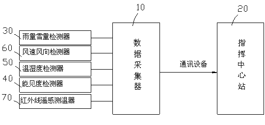
[0028] Such as figure 1 As shown, a meteorological monitoring system includes a data collector 10 for collecting various detectors. The data collector 10 processes the signals obtained by the detectors and transmits them to the command center station 20 through communication equipment. The data collector 10 uses AC There are two modes of power supply and battery intelligent power supply to ensure that the data collector 10 can continue to work when the collection system is powered off due to a fault. Detector 50, wind direction and wind speed detector 60 and infrared remote sensing road surface temperature measuring device 70 carry out data collection and analysis on dust, fog, visibility parameters, road surface temperature, wind direction and ...
PUM
 Abstract
Description
Claims
Application Information