
Optical reading heat-mechanical infrared detector structure and manufacturing method thereof

An infrared detector and optical readout technology, applied in optical radiation measurement, scientific instruments, final product manufacturing, etc., can solve problems such as long response time of thermal imaging, failure of pixel energy to be transmitted and lost in time, thermal crosstalk, etc., to achieve The effects of improving temperature response sensitivity, increasing optical fill factor, and accelerating thermal imaging rate

Active Publication Date: 2015-06-10
INST OF MICROELECTRONICS CHINESE ACAD OF SCI
View PDF3 Cites 0 Cited by
  • Summary
  • Abstract
  • Description
  • Claims
  • Application Information

AI Technical Summary

Problems solved by technology

The FPA with a substrate can transfer heat to the substrate in time to increase the thermal imaging rate, but due to the existence of the substrate, about 40% of the infrared radiation is absorbed and reflected by the substrate, which reduces the infrared absorption efficiency. In addition, the sacrificial layer The release process is complicated, which often causes adhesion between the structural layer and the substrate, resulting in pixel failure
However, the infrared FPA with no substrate and fully hollowed out improves the infrared absorption efficiency, but due to its fully hollowed out feature, the energy of the pixels cannot be transmitted out in time and lost, resulting in heat transfer between each pixel, and each pixel cannot be independent Work, thermal crosstalk phenomenon is serious, thermal imaging response time is long, and the reduction of device size has a huge impact on its performance, which limits the reduction of pixel size

Method used


Image

  • Optical reading heat-mechanical infrared detector structure and manufacturing method thereof
  • Optical reading heat-mechanical infrared detector structure and manufacturing method thereof
  • Optical reading heat-mechanical infrared detector structure and manufacturing method thereof

Examples


Embodiment Construction

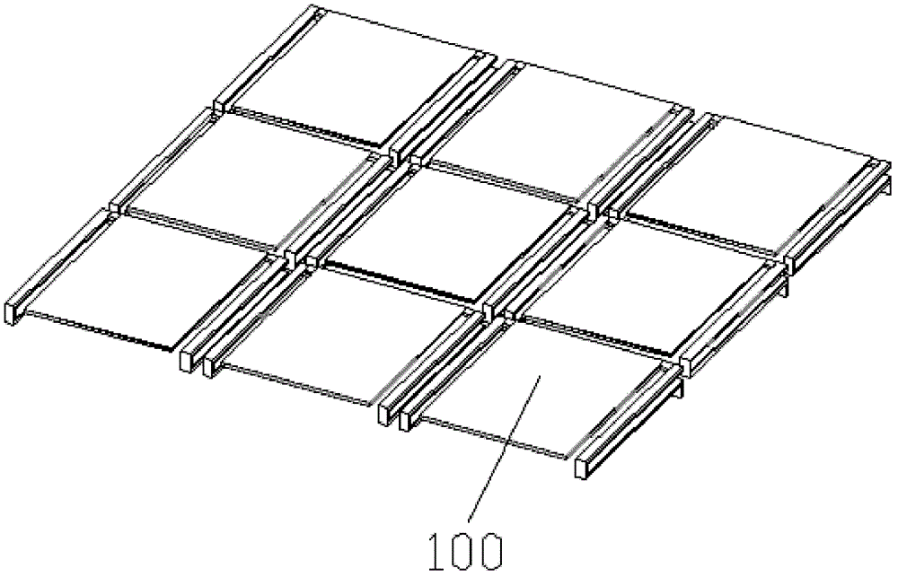
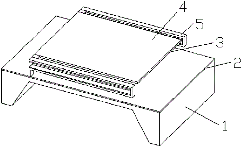
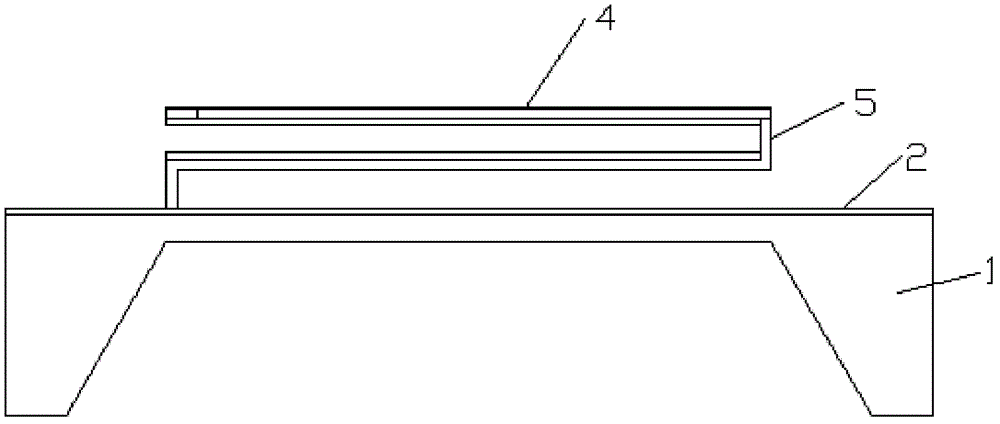
[0049] An optical readout thermal-mechanical infrared detector structure, including several pixel units 100 distributed in an array, each pixel unit includes: a substrate 1, a supporting layer 2, an infrared absorption layer 3, a reflector 4 and The double-material cantilever beam 5, the support layer is located on the upper side of the substrate, and the center of the lower side of the substrate is semi-hollowed out; the space between the infrared absorbing layer is located above the upper side of the supporting layer, and the reflector is located on the upper side of the infrared absorbing layer; There are two material cantilever beams, which are arranged symmetrically on the upper side of the support layer in parallel intervals; each double-material cantilever beam includes upper and lower beams 6 and lower beams 7 arranged in parallel and spaced up and down, and the lower beam is composed of the first non-metallic layer 8 and the second It consists of a metal layer 9, the f...


PUM


Abstract

The invention discloses an optical reading heat-mechanical infrared detector structure and a manufacturing method thereof. The optical reading heat-mechanical infrared detector structure comprises a plurality of pixel units distributed in an array mode, wherein each pixel unit comprises a substrate, a supporting layer, an infrared absorbing layer, a light reflection plate and double-material cantilever beams. The infrared detector structure not only inherits advantages of a focus plane array (FPA) with a substrate and a fully-hollowed-out FPA, but also overcomes defects existing in the FPA with the substrate and the fully-hollowed-out FPA. The FPA with the substrate structure improves infrared absorption efficiency, improves temperature uniformity of a film area compared with the fully-hollowed-out FP, enables pixels to be capable of working independently, and promotes a heat response rate, meanwhile the pixels are manufactured on the supporting layer, an extra supporting frame is needless, and a duty ratio is improved; and in addition, according to structural design of the deformation cantilever beams in an up-and-down overlaying mode, not only is temperature response sensitivity improved, but also optical fill factors are improved, and convenience is brought to development of pixels with small sizes.

Description

technical field [0001] The invention relates to an optical readout thermal-mechanical infrared detector structure and a manufacturing method thereof. Background technique [0002] Infrared technology is widely used in various industries such as industry, agriculture, medical treatment, and science. Infrared imaging, infrared temperature measurement, infrared physiotherapy, infrared detection, infrared alarm, infrared remote sensing, and infrared heating are advanced technologies that various industries are competing to choose. In the military, infrared imaging, infrared reconnaissance, infrared tracking, infrared guidance, infrared early warning, infrared confrontation, etc. are indispensable tactical and strategic means in modern and future warfare. [0003] Infrared detectors are used to convert invisible infrared radiation into visible images. According to different detection principles, traditional detectors can be divided into two categories: photoelectric infrared det...

Claims


Application Information

Patent Timeline
Patent Type & Authority Patents(China)
IPC IPC(8): H01L31/101H01L31/18G01J5/00
CPCY02P70/50
Inventor 刘瑞文焦斌斌孔延梅尚海平李志刚卢狄克高超群陈大鹏
Owner INST OF MICROELECTRONICS CHINESE ACAD OF SCI
Learn More