
Device and method for cleaning ammonia distillation system

A cleaning device and ammonia distillation technology, which is applied in the field of coking, can solve the problems of poor heat transfer effect, time-consuming and labor-intensive waste of resources, etc. in waste water heat exchangers and waste water coolers, so as to shorten the cleaning time, improve the working environment and reduce labor intensity Effect

Active Publication Date: 2014-12-31
ANGANG STEEL CO LTD
View PDF8 Cites 0 Cited by
  • Summary
  • Abstract
  • Description
  • Claims
  • Application Information

AI Technical Summary

Problems solved by technology

It is mainly manifested in the process of gas purification, a series of problems such as poor heat exchange effect of waste water heat exchanger and waste water cooler, blockage of waste water pipeline and poor ammonia distillation effect of ammonia distillation tower in the ammonia distillation system, so that the amount of steam used in the ammonia distillation process Increased, increased energy consumption, poor operation
Not only did it cause certain difficulties for the smooth production of the ammonium sulfate process, but also made the import index of phenol cyanide wastewater unqualified, resulting in the export index of phenol cyanide wastewater not meeting the national secondary discharge standards.
For this reason, the ammonia distillation system had to be thoroughly cleaned. However, since the waste liquid after cleaning has no external discharge pipeline, it is connected to a rubber tube and then discharged to the mechanized clarifier tank. The labor intensity of workers, and affect the smooth progress of production, and there will be waste liquid leakage to the ground, which not only causes a waste of resources, but also seriously pollutes the environment

Method used


Image

  • Device and method for cleaning ammonia distillation system

Examples


Embodiment Construction

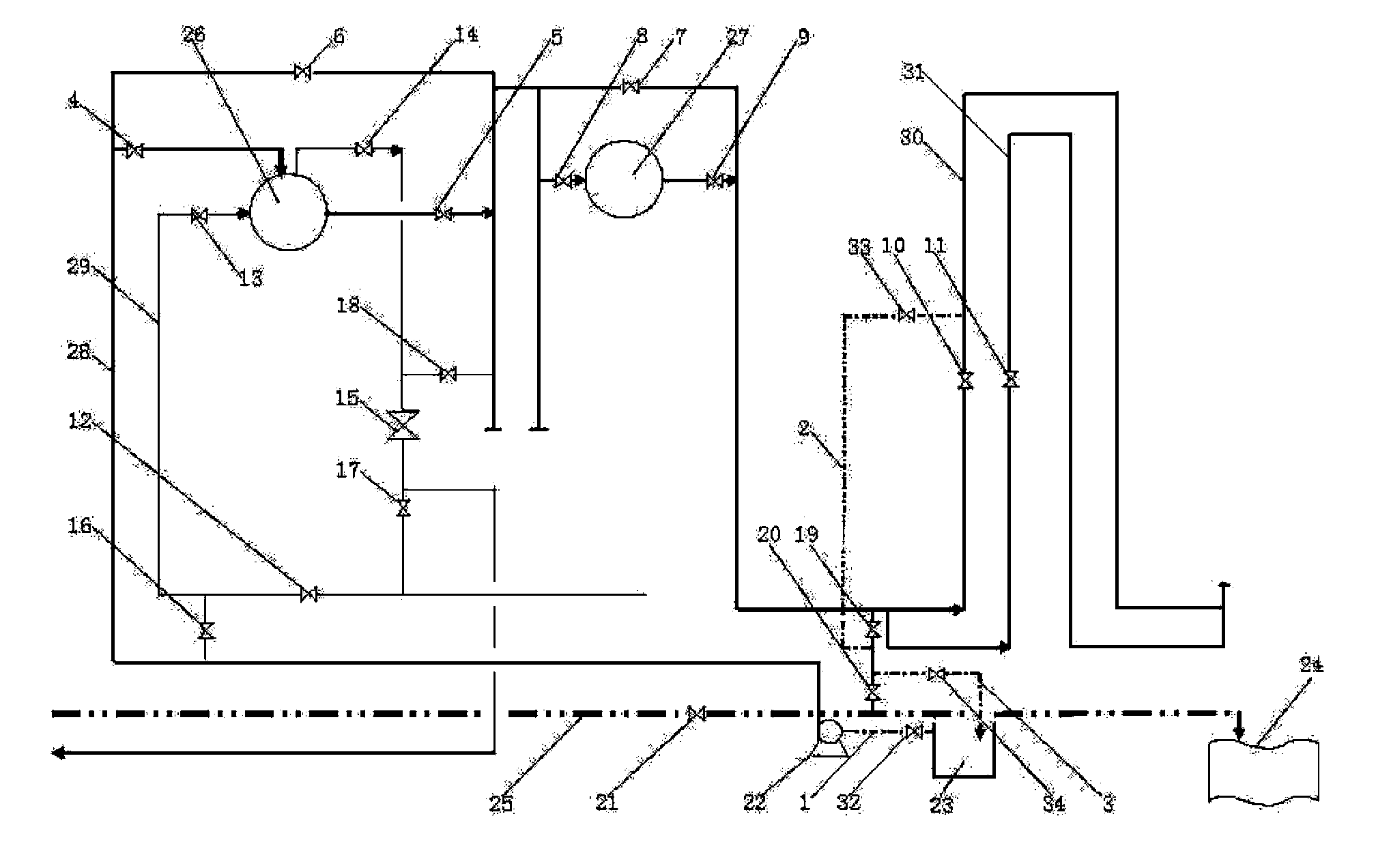
[0020] Depend on figure 1 It can be seen that the ammonia distillation system cleaning device of the present invention is based on the original waste water heat exchanger 26, the waste water cooler 27 and the waste water process pipeline 28 connected thereto, the remaining ammonia water process pipeline 29, the old waste water pipeline 30 and the new waste water pipeline 31, Between the centrifugal pump 22 of the waste water process pipeline 28 and the phenol cyanide auxiliary agent input tank 23, an auxiliary agent pipe 1 and valve nineteen 32 are added; One end of pipe 2 is connected between valve sixteen 19 and valve seventeen 20, and the other end is connected on the old waste water pipe 30 at the rear of valve seven 10; the old waste water pipe 30 between valve sixteen 19 and valve seventeen 20 Connect a return pipe 3 and valve 21 34 on the top, and the other end of the return pipe 3 communicates with the phenol cyanide additive delivery tank 23; connect the slag discharg...


PUM


Abstract

The invention provides a device and a method for cleaning ammonia distillation system. An original waste water heat exchanger, an original waste water cooler, and an original waste water process pipeline, an original remaining ammonia process pipeline, an original old waste water pipeline and an original new waste water pipeline which are connected with the original waste water heat exchanger and the original waste water cooler are utilized, and an auxiliary agent pipe, a waste water pipe, a return pipe, a slag discharge pipe and corresponding valves are additionally arranged; and the cleaning of an ammonia device and the pipelines is realized by opening and closing the different valves. The cleaning time is greatly shortened, the whole cleaning process only requires 12 hours, the loss of ammonium sulfate can be reduced, and the yield of ammonium sulfate is increased; waste liquid after cleaning is directly pumped in a mechanized settle tank for recovery utilization, more than 20 tons of cleaning agent and tar mixture can be recycled during cleaning work every time, and the environmental pollution is prevented while the waste of resources is reduced; and simultaneously, the workload of cleaning and processing can be greatly reduced, and the labor intensity of on-site workers is lightened.

Description

technical field [0001] The invention belongs to the technical field of coking, and in particular relates to a device and method for cleaning ammonia water equipment and pipelines in an ammonia distillation system and recovering cleaning waste liquid. Background technique [0002] The 7-meter coke oven is currently the largest coke oven in China. Although the supporting gas purification system has been gradually improved since the start of construction, some operational problems have gradually appeared in the actual production process. It is mainly manifested in the process of gas purification, a series of problems such as poor heat exchange effect of waste water heat exchanger and waste water cooler, blockage of waste water pipeline and poor ammonia distillation effect of ammonia distillation tower in the ammonia distillation system, so that the amount of steam used in the ammonia distillation process Increase, energy consumption increases, and the operation is not smooth. ...

Claims


Application Information

Patent Timeline
Patent Type & Authority Patents(China)
IPC IPC(8): B08B3/08B08B9/027C23G3/02C23G3/00
Inventor 赵恒波武斌马银华梁媛媛
Owner ANGANG STEEL CO LTD
Learn More