Bias correction method of drill bushing mounting hole of drill plate

A technology of deviation correction and mounting holes, which is applied in the direction of drilling/drilling equipment, drilling templates for workpieces, boring machines/drilling machine parts, etc., which can solve the problems of long construction period, low efficiency, and inability to meet urgent processing, etc., to achieve The effect of shortening the construction period and improving efficiency

Inactive Publication Date: 2013-07-17
HARBIN
View PDF5 Cites 16 Cited by
  • Summary
  • Abstract
  • Description
  • Claims
  • Application Information

AI Technical Summary

Problems solved by technology

Its disadvantages are: remanufacturing the drill sleeve requires mechanical processing and heat treatment, long construction period, low efficiency, and cannot meet the needs of urgent processing

Method used


Image

  • Bias correction method of drill bushing mounting hole of drill plate
  • Bias correction method of drill bushing mounting hole of drill plate

Examples


Embodiment 1

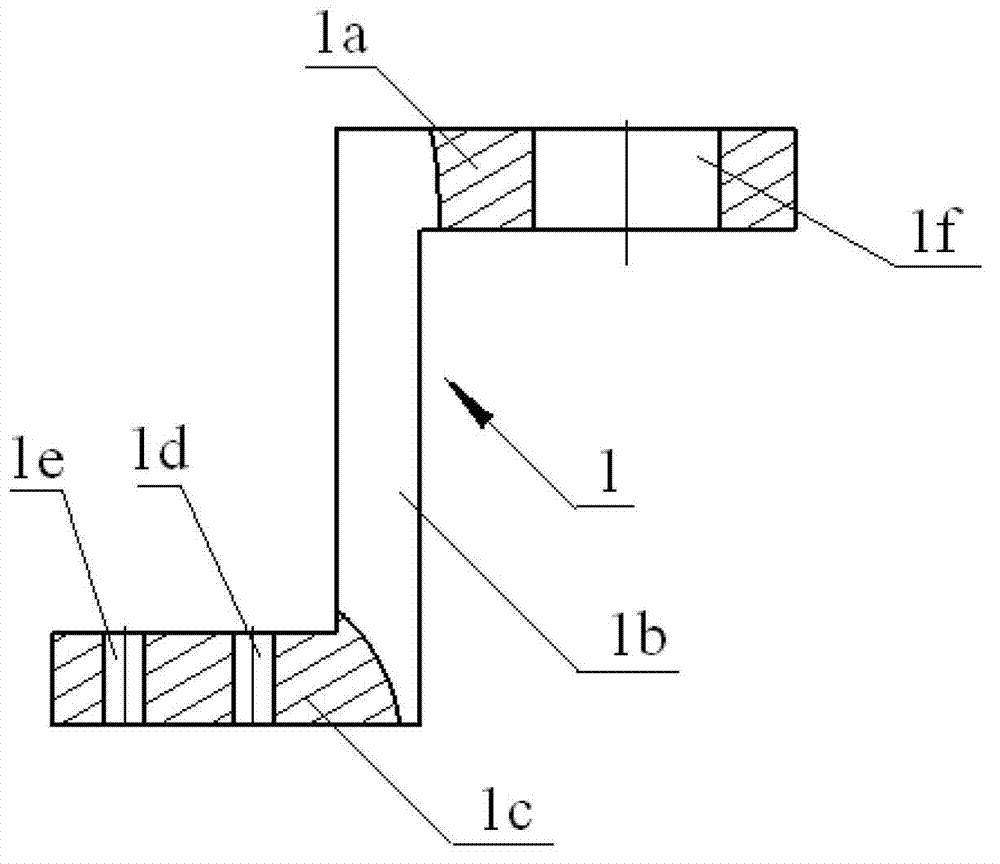
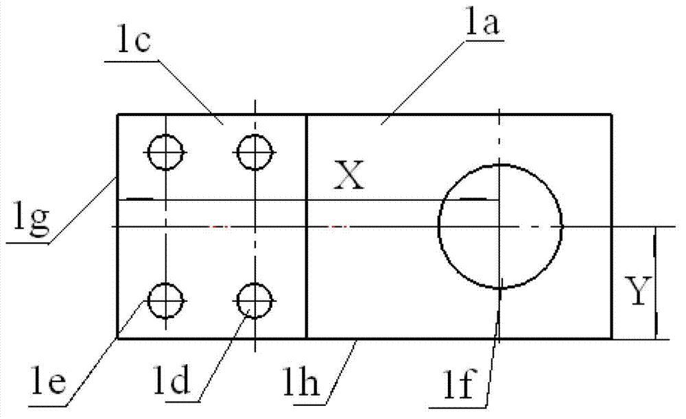
[0017] Example 1, there is a drill sleeve installation hole with a diameter of Φ12mm on a drilling template of a fixture, the distance from the axis of the drill sleeve installation hole to the first positioning surface is 150mm, and the existing deviation is 0.1mm. The distance from the axis to the second positioning surface is 50mm, and the existing deviation is 0.06mm. The steps to correct the deviation of the drill sleeve installation hole are:

[0018] 1.1. Measure the deviation value of the drill sleeve installation hole: use the three-coordinate measuring machine tool to measure the deviation value of the drill sleeve installation hole ΔX is 0.1mm, and ΔY is 0.06mm;

[0019] 1.2. Eccentric reaming: fix the drilling template on the boring machine, firstly align the mounting hole of the drill sleeve, make the distance from the axis of the boring machine to the first positioning surface 150mm, the alignment deviation ΔX1 is 0.01mm, and the axis of the boring machine to the ...


PUM


Abstract

The invention belongs to the mechanical processing technology, and relates to a bias correction method of a drill bushing mounting hole of a drill plate. The method for correcting the drill bushing mounting hole comprises the following steps of: measuring a bias value of the drill bushing mounting hole; eccentrically chambering; installing a correction bushing; and installing a drill bushing provided with a correction bushing in the chambered drill bushing mounting hole. According to the bias correction method of the drill bushing mounting hole of the drill plate, a drill bushing does not need to be newly manufactured, thereby shortening the working period, improving the efficiency and meeting the requirement of nasty piece processing.

Description

technical field [0001] The invention belongs to the mechanical processing technology, and relates to a method for correcting the deviation of the installation hole of a drill template drill sleeve. Background technique [0002] Large fixtures are often installed with many figure 1 , 2 As shown in the drilling formwork 1, the drilling formwork 1 is composed of an upper rectangular drill sleeve mounting plate 1a, a middle rectangular support plate 1b and a lower rectangular positioning plate 1c. The left end of the drill sleeve installation plate 1a is vertically connected to the upper end of the support plate 1b as a whole, and the lower end of the support plate 1b is vertically connected to the right end of the positioning plate 1c as a whole, and there are two positioning pin holes 1e and two screws on the positioning plate 1c Via 1d. The positioning plate 1c is fixed on the large jig by two positioning pins and two screws. There is a drill sleeve installation hole 1f o...

Claims


Application Information

Patent Timeline
Patent Type & Authority Applications(China)
IPC IPC(8): B23P6/00B23B47/28B23B49/02
Inventor 刘国全孙大伟李广伟王龙李野
Owner HARBIN
Why Eureka
Try Eureka