Silt-preventing function-based sediment overflow ballast tank

An overflow pressure and sediment prevention technology, which is applied in some cabins, ships, and hulls in the hull, can solve the problems of increased hull safety hazards and inconvenient removal, and achieves the goal of reducing work difficulty, maintaining consistency, and reducing safety hazards. Effect

Active Publication Date: 2013-07-17
DALIAN SHIPBUILDING IND
View PDF7 Cites 6 Cited by
  • Summary
  • Abstract
  • Description
  • Claims
  • Application Information

AI Technical Summary

Problems solved by technology

[0004] The present invention aims to solve the problems of prior art ballast tanks, where sediment and silt are mainly deposi

Method used


Image

  • Silt-preventing function-based sediment overflow ballast tank
  • Silt-preventing function-based sediment overflow ballast tank
  • Silt-preventing function-based sediment overflow ballast tank

Examples


experiment approach 64

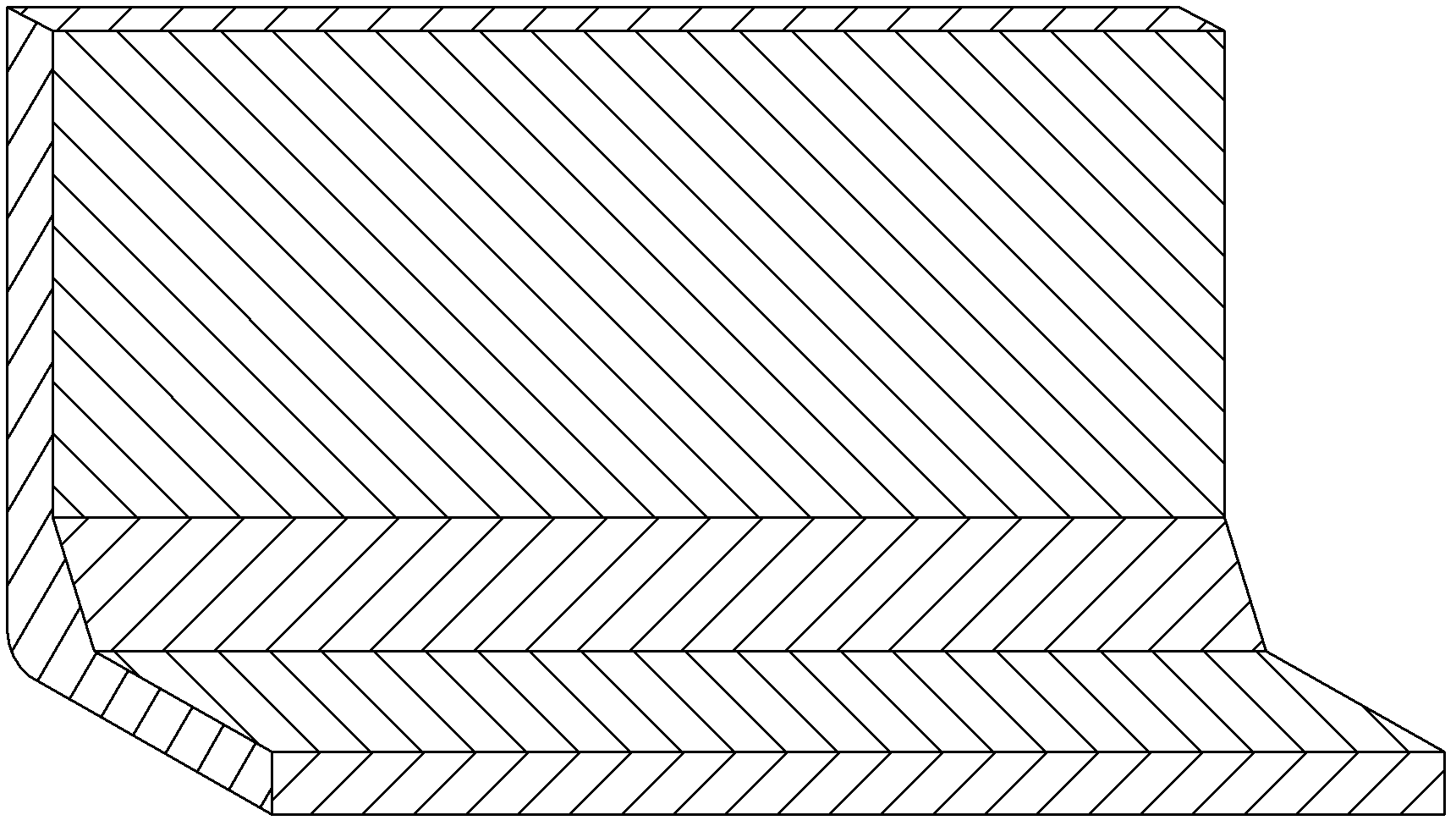
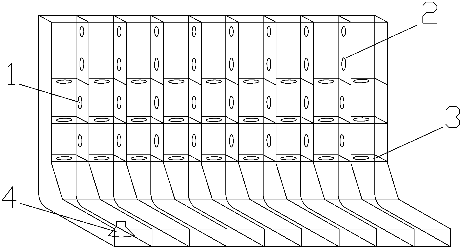
[0030]The present invention is based on experiments, and uses CFD fluid analysis software to carry out a large number of calculations, compare, analyze and demonstrate to obtain the above conclusions. Among them, there are 12 intermediate process schemes and 64 experimental schemes. The invention can deposit 30-40% of the silt in the side sedimentation tank, wherein the silt particles with larger particle diameters that can be deposited in a short time are mainly deposited. The large opening of each rib member 7 of the ballast tank is consistent with the height of the horizontal truss member. When the ballast water is exchanged next time, the ballast water flows along the horizontal truss member, and the side ballast tank can be cleaned automatically. It is easy to operate and saves manpower and material resources. More importantly, the ballast water after the overflow of the side settling tank mainly contains small-sized sediment particles that are not easy to settle in a sh...


PUM


Abstract

The invention discloses a silt-preventing function-based sediment overflow ballast tank, which comprises ballast tank spaces which are positioned at a board and a hull bottom and are communicated with each other, wherein a sediment tank with an enclosed lower part is independently isolated from the ballast tank space at the board; the upper part of the sediment tank is provided with upper through holes communicated with other spaces of the ballast tank and used for overflow; and one side of the bottom of the sediment tank is provided with a water inlet/outlet. The board of the ballast tank is provided with the independent sediment tank, so that silt can be controlled to be precipitated in the easily cleaned sediment tank as far as possible; and the fundamental watertight division is not changed, the silt-preventing function-based sediment overflow ballast tank is kept consistent with the conventional ballast tank, and the operating complexity of crew is not improved. By the silt-preventing function-based sediment overflow ballast tank, the working difficulty of cleaning the silt is reduced, and the potential safety hazard of a ship is reduced further.

Description

technical field [0001] The invention relates to the field of ship subdivision and structural design, more specifically, to the structural improvement of ship ballast tanks. Background technique [0002] Such as figure 1 Shown, the ballast tank of prior art comprises the enclosed space ( figure 1 L-shaped overall structure shown). Among them, such as figure 2 As shown in the prior art ballast tank, the ballast tank located on the side is divided into small partitions alternately by horizontal horizontal truss members 3 and longitudinal rib members 2 , and each partition is connected by holes 1 . The ballast tanks at the bottom of the ship consist of image 3 The upper middle inner bottom plate 22 and the lower outer bottom plate 23 are formed, and the longitudinal ribs 21 are arranged at intervals vertically on the inner bottom plate 22 and the outer bottom plate 23 . figure 1 Also shown in the ballast tank bottom suction port 4 for ballast tank water inlet / outlet at th...

Claims


Application Information

Patent Timeline
IPC IPC(8): B63B11/04
Inventor 蔡洙一孙晓楠李玉平赵金文王景洋姚云熙沙明文
Owner DALIAN SHIPBUILDING IND
Why Eureka
Try Eureka