Image processing method, conference terminal, conference place electronic system and video conference system

An electronic system and video conferencing technology, which is applied in the field of video communication, can solve problems such as affecting the display effect of video images, unable to display images, enlargement, etc., and achieve the effects of improving display effects, flexible layout positions, and reducing blind spots

Inactive Publication Date: 2013-07-17
HUAWEI TECH CO LTD
View PDF4 Cites 18 Cited by
  • Summary
  • Abstract
  • Description
  • Claims
  • Application Information

AI Technical Summary

Problems solved by technology

However, since the camera installed in the middle of the projection screen is equivalent to an occluder, the optical path of the projected image of the rear projection projector forms a blind area on the projection screen that cannot display images due to the occlusion of the camera. The area of ​​the blind area is larger than the front projection area of ​​the camera.
If you want to shoot high-definition images, you need to use a larger camera, and the increase in the size of the camera will inevitably increase the area of ​​​​the blind spot; in addition, in order to save the space of the venue, the distance between the projector and the projection screen must be closer and closer. However, as the projector gets closer to the projection screen, the area of ​​the blind zone increases accordingly, which affects the display effect of the video image.

Method used


Image

  • Image processing method, conference terminal, conference place electronic system and video conference system
  • Image processing method, conference terminal, conference place electronic system and video conference system
  • Image processing method, conference terminal, conference place electronic system and video conference system

Examples


Embodiment Construction

[0032] In order to make the purpose, technical solutions and advantages of the embodiments of the present invention clearer, the technical solutions in the embodiments of the present invention will be clearly and completely described below in conjunction with the drawings in the embodiments of the present invention. Obviously, the described embodiments It is a part of embodiments of the present invention, but not all embodiments. Based on the embodiments of the present invention, all other embodiments obtained by persons of ordinary skill in the art without making creative efforts belong to the protection scope of the present invention.

[0033] The serial numbers of the following embodiments of the present invention are for description only, and do not represent the advantages and disadvantages of the embodiments.

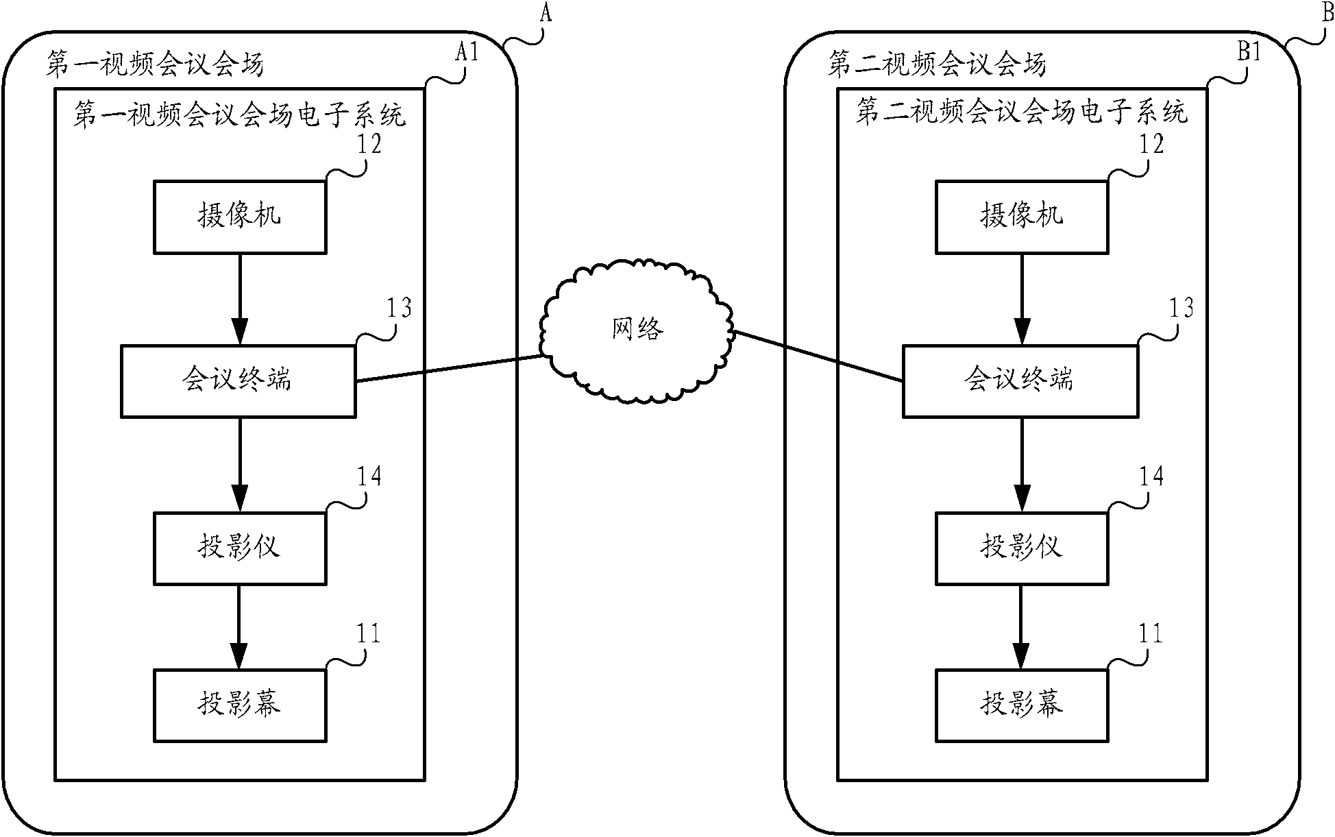
[0034] Figure 1a It is a schematic structural diagram of a video conferencing system provided by Embodiment 1 of the present invention. The video conference sys...


PUM


Abstract

The invention discloses an image processing method, a conference terminal, a conference place electronic system and a video conference system. The electronic system comprises a projection screen, a camera located on one side of the projection screen, the conference terminal and a projector located on the other side of the projection screen. A viewfinder is arranged at a pre-determined position of the projection screen, the camera is used for shooting a first video image through the viewfinder and sending the first video image, and the conference terminal is used for receiving the first video image sent by the camera, sending the first video image to other video conference place electronic systems, receiving second video images sent by other electronic systems, determining image areas corresponding to the viewfinder in the second video images, performing image brightness blocking on the determined image areas and sending the determined image areas. The projector is used for receiving and displaying the second video images sent by the conference terminal and experiencing image brightness blocking in a projected mode. The image processing method, the conference terminal, the conference place electronic system and the video conference system save conference place space and improve projection display effect of video images.

Description

technical field [0001] Embodiments of the present invention relate to video communication technology, and in particular to an image processing method, a conference terminal, a venue electronic system, and a video conference system. Background technique [0002] With the development of video communication technology, telepresence services are increasingly emerging. In the telepresence service, each video conference venue is equipped with multiple cameras, multiple display screens and conference terminals, corresponding to participants in different locations. For example, a typical telepresence conference site includes multiple user areas, and each user area corresponds to a microphone (MIC), a camera, a display, conference terminals and other devices. During the video conference, any camera collects the image of its corresponding user area and transmits the captured image to its corresponding conference terminal. The conference terminal encodes the received image and sends i...

Claims


Application Information

Patent Timeline
Patent Type & Authority Applications(China)
IPC IPC(8): H04N7/14H04N7/15G03B17/54
Inventor 吴姣黎赵光耀
Owner HUAWEI TECH CO LTD
Why Eureka
Try Eureka