
Method and system for controlling a filter

A filter and suction pipe technology, applied in chemical instruments and methods, separation methods, dispersed particle filtration, etc., can solve problems such as reduced generator efficiency and reduced compressor performance.

Inactive Publication Date: 2013-07-17
GE ENERGY PRODS FRANCE
View PDF5 Cites 4 Cited by
  • Summary
  • Abstract
  • Description
  • Claims
  • Application Information

AI Technical Summary

Problems solved by technology

The performance of the compressor is reduced, thereby reducing the efficiency of the generator of the turbine

Method used


Image

  • Method and system for controlling a filter

Examples


Embodiment Construction

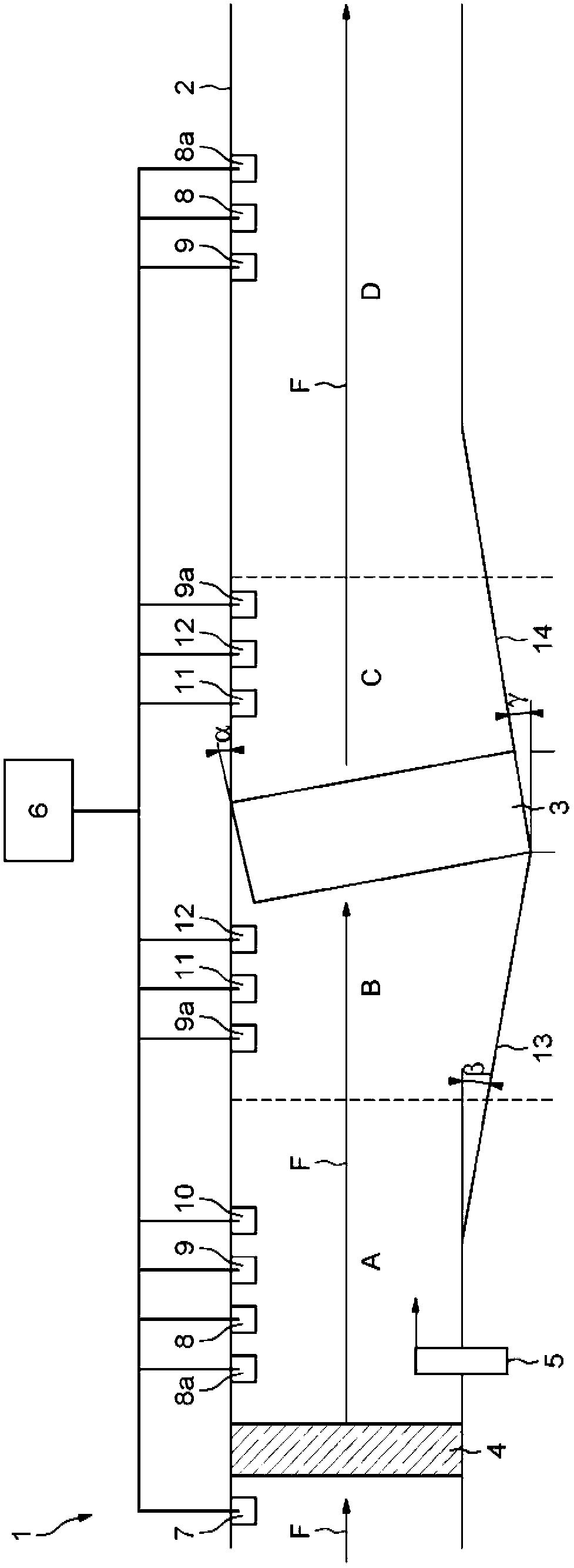
[0024] As shown in the drawings, the monitoring system 1 includes a test pipeline 2 in which a filter 3 to be tested is installed and in which a test procedure is carried out to determine the salt retention capacity of the filter 3 . Thus, the test duct 2 has suitable supports (not shown) for the filter 3 to position the filter in the duct in transverse direction, in the path of the incident air flow indicated by the arrow F.

[0025] A high-performance filter 4 called a "High Efficiency Particulate Air (HEPA)" filter is installed at the inlet of the test duct 2 to supply high-quality air in the duct, especially in the different measurement areas A, B, C and D. Air. The measurement area A is located between the HEPA filter 4 and the filter 3 to be tested until it adjoins the area B located directly upstream of the filter 3 . Zone C is located directly downstream of filter 3 and zone D is located downstream of zone C. The test conduit 2 comprises means 5 for injecting a flow ...


PUM


Abstract

According to the method for controlling a filter (3) for an air intake duct of a turbine: the filter (3) is exposed to an incident flow of sprayed salt water; and parameters of the flow on either side of the filter, which are representative of the salt retention capability of the filter, are measured.

Description

technical field [0001] The invention relates to filters for suction lines in turbomachines, especially gas turbines. [0002] More specifically, the present invention relates to filters for installations in saltwater rich environments. Background technique [0003] It is well known that the air contains dust particles, most of which are on the order of a few microns. The turbine is very susceptible to the adverse effects of these dust particles, given that the turbine draws in a considerable amount of air. [0004] The atmosphere can contain dust, fog, rain, salt water, carbon particles, and more. As a result, the air sucked in by the turbine may cause corrosion and contamination within the ducts of the turbine, especially in the air compressor, which is located at the forefront of the duct. The performance of the compressor is reduced, thereby reducing the efficiency of the generator of the turbine. [0005] To reduce these risks, a filter is usually placed at the inlet...

Claims


Application Information

Patent Timeline
IPC IPC(8): B01D46/44G01N15/06
CPCF05B2260/80B01D46/446G01N15/08B01D46/442B01D46/44G01N15/06G01N2015/084B01D46/444
Inventor P.克劳唐
Owner GE ENERGY PRODS FRANCE
Learn More