Video display method, video display panel, and video display apparatus

An image display and image display technology, which is applied in the directions of identification devices, image communication, static indicators, etc., can solve the problems of image quality degradation, color balance destruction, etc., and achieve the effect of suppressing image quality degradation

Inactive Publication Date: 2013-07-17
PANASONIC INTELLECTUAL PROPERTY CORP OF AMERICA
View PDF7 Cites 15 Cited by
  • Summary
  • Abstract
  • Description
  • Claims
  • Application Information

AI Technical Summary

Problems solved by technology

Therefore, in the image display unit 110, when the shapes of the respective sub-pixels corresponding to R, G, and B constituting one pixel are different, or when the respective sub-pixels are not uniformly arranged in one pixel, the image separation unit 120 separates the sub-pixels. The color balance of the right-eye image X1 or left-eye image X2 is broken, and the quality is reduced

Method used


Image

  • Video display method, video display panel, and video display apparatus
  • Video display method, video display panel, and video display apparatus
  • Video display method, video display panel, and video display apparatus

Examples


Embodiment 1

[0082] First, regarding the video display method, video display panel, and video display device according to Embodiment 1 of the present invention, refer to the attached Figure 1 side to explain.

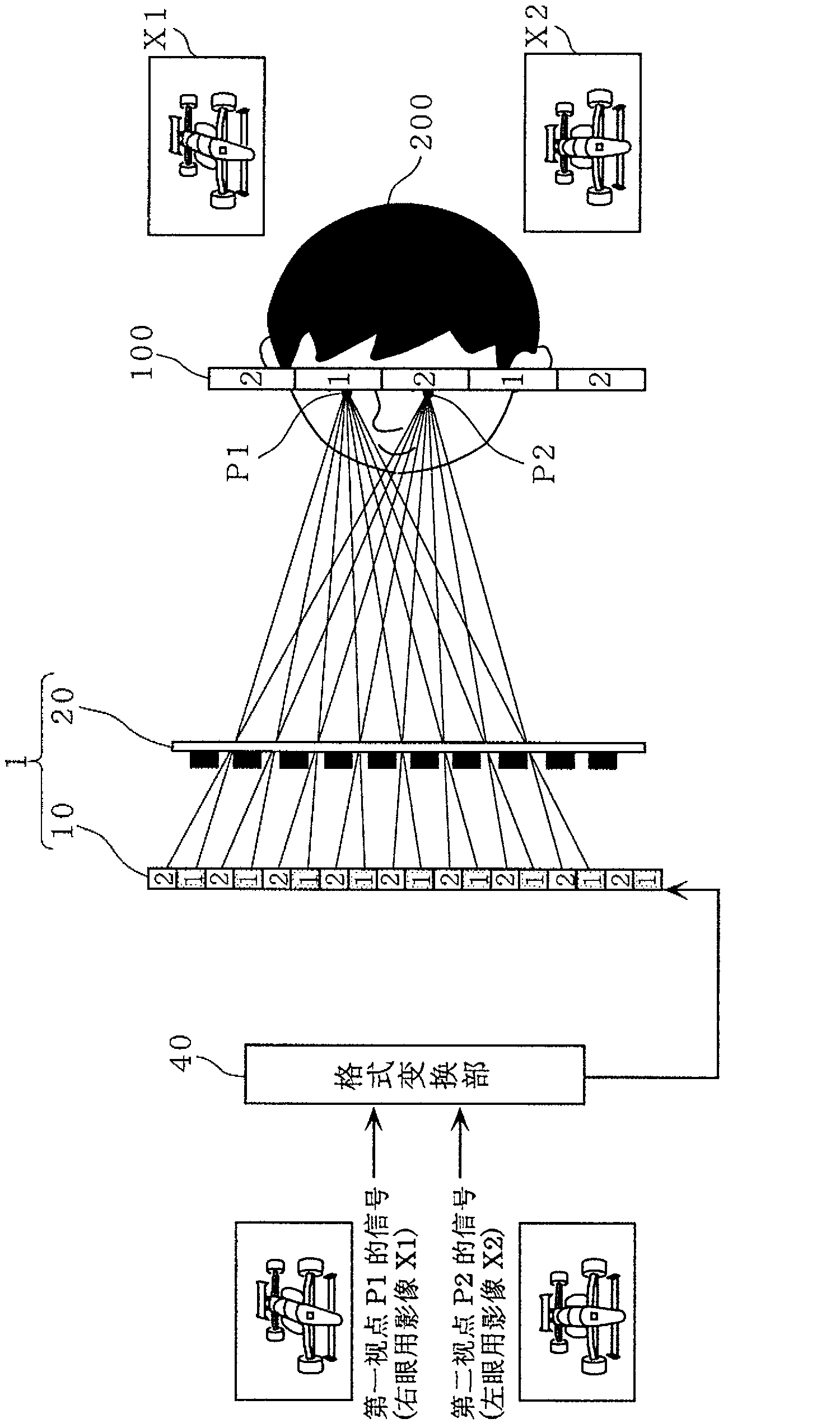
[0083] figure 1 It is a diagram showing an outline of a video display method according to Embodiment 1 of the present invention capable of stereoscopic viewing with the naked eye. exist figure 1 When a stereoscopic video can be seen from signals (video X1 for right eye and video X2 for left eye) of two viewpoints (first viewpoint P1 (right eye) and second viewpoint P2 (left eye)) (2 parallax) principle. In other words, the viewer 200 on the video display area (viewing position) 100 sees the video X1 for the right eye as the signal of the first viewpoint P1 with the right eye among the signals of the two viewpoints, and sees the video X1 for the second viewpoint as the signal of the second viewpoint P1 with the left eye. The left-eye image X2 of the signal of the viewpoint P2 ...

Embodiment 2

[0132] use below Figure 7A as well as Figure 7B The image display panel 2 according to the second embodiment of the present invention will be described. Figure 7A as well as Figure 7B It is a diagram schematically showing the relationship between the image display unit and the image separation unit of the video display panel according to the second embodiment of the present invention. in addition, Figure 7A Indicates the image seen at the first viewpoint P1, Figure 7B Indicates the image seen at the second viewpoint P2.

[0133] In this embodiment, the pixel configuration of the image display portion of the video display panel 2 is different from that in the first embodiment.

[0134] Such as Figure 7A as well as Figure 7B As shown, in the image display panel 2 according to this embodiment, the pixels of the display portion 11A of the image display portion 10A are configured such that the size of a plurality of sub-pixels in one pixel is different from the size ...

Embodiment 3

[0161] Next, use Figure 10 A video display device according to Embodiment 3 of the present invention will be described. Figure 10 It is a diagram showing a schematic configuration of a video display device according to Embodiment 3 of the present invention. The video display device according to this embodiment can be implemented as a liquid crystal display device, a plasma display device, or an organic electroluminescence display device, and for example, the video display panel 1 according to the above-mentioned embodiment can be used. By using the video display panel according to this embodiment, it is easy to incorporate the video display method according to the present invention into various devices, and it is possible to view a three-dimensional image with excellent color balance and less moiré.

[0162] In addition, in the image display device according to this embodiment, if Figure 10 As shown in (a) to (c), for example, the video display panel 1 according to the fi...


PUM


Abstract

This video display panel (1) has: an image display unit (10) for displaying a composite image including a plurality of different images, the image display unit having a plurality of pixels (12); and an image separation unit (20) for separating the composite image displayed on the image display unit (10) into a plurality of different images, using an opening part (22) and a light-shielding part (23), the image separation unit being disposed facing the image display unit (10). Each of the plurality of pixels is composed of a plurality of sub-pixels individually having a light-emitting region, and a plurality of sub-pixels within a single pixel are not of a size obtained by equally dividing the single pixel; rather, the opening part opens in an inclined direction and a border line between the opening part and the light-shielding part either is in parallel with a connecting line of lines linking the centers of gravity of neighboring sub-pixels from among the plurality of sub-pixels for displaying an image corresponding to each of the plurality of different images or a connecting line of lines linking the centers of gravity of neighboring light-emitting regions; or, alternatively, is a connecting line of lines linking the center point of the centers of gravity of neighboring sub-pixels or a connecting line of lines linking the center point of the centers of gravity of neighboring light-emitting regions.

Description

technical field [0001] The present invention relates to a method for displaying stereoscopic images with naked eyes, an image display panel and an image display device, in particular to a parallax barrier type stereoscopic image display panel. Background technique [0002] Conventionally, there is known a video display device that displays stereoscopic video (three-dimensional video) with naked eyes without using special glasses. For example, a parallax barrier (parallax barrier) and a lenticular lens (spectroscopy unit) are arranged on the viewer side of a display such as a liquid crystal display or a plasma display (PDP), etc., and the light from the synthesized image is separated to display a stereoscopic image. The image includes a right-eye image and a left-eye image displayed on the display. [0003] use Figure 15 An example of a conventional method in which video is displayed so that a viewer sees a stereoscopic video with naked eyes will be described. Figure 15 It...

Claims


Application Information

Patent Timeline
Patent Type & Authority Applications(China)
IPC IPC(8): G02B27/22G02F1/1335G09F9/00G09G3/20G09G5/36G02B30/27G02B30/31
CPCG02B27/22G09G2300/0439G09G3/20G02F1/1335G09G2300/0469G09G5/36G09G2320/0204G09F9/00G09G5/14H04N13/0422G02B27/2214H04N13/0415G09G3/003H04N13/0409H04N13/324H04N13/31H04N13/317G02B30/27G02B30/31
Inventor 国枝伸行渡边辰巳增谷健
Owner PANASONIC INTELLECTUAL PROPERTY CORP OF AMERICA
Why Eureka
Try Eureka