Honeysuckle flower picking machine
A technology for picking machines and honeysuckle, which is applied in the directions of picking machines, harvesters, agricultural machinery and implements, etc., can solve the problems of uneven size and length of honeysuckle, material content and water loss of honeysuckle, loss of growers, etc.
- Summary
- Abstract
- Description
- Claims
- Application Information
AI Technical Summary
Problems solved by technology
Method used
Image

Examples
Embodiment 1
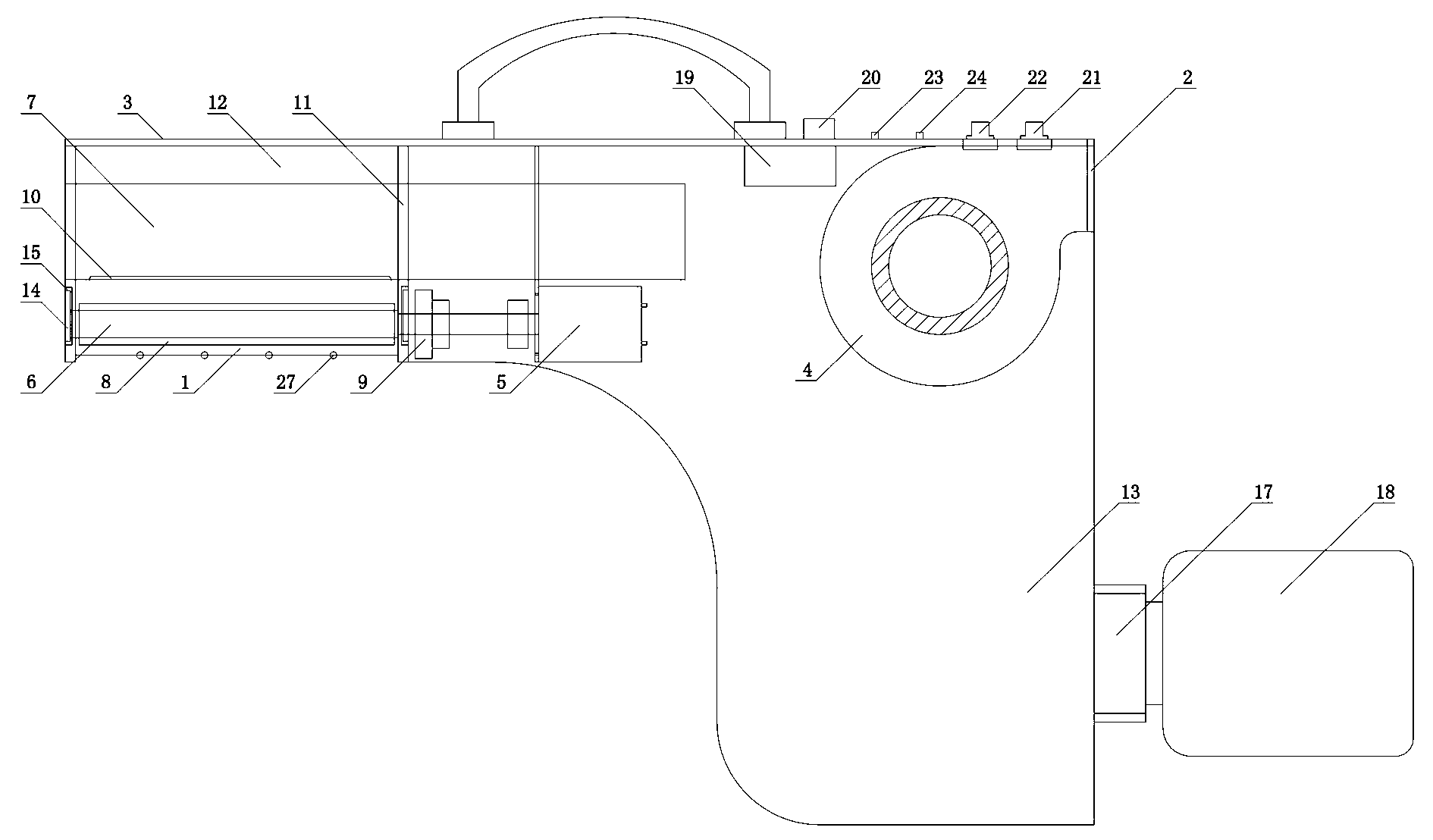
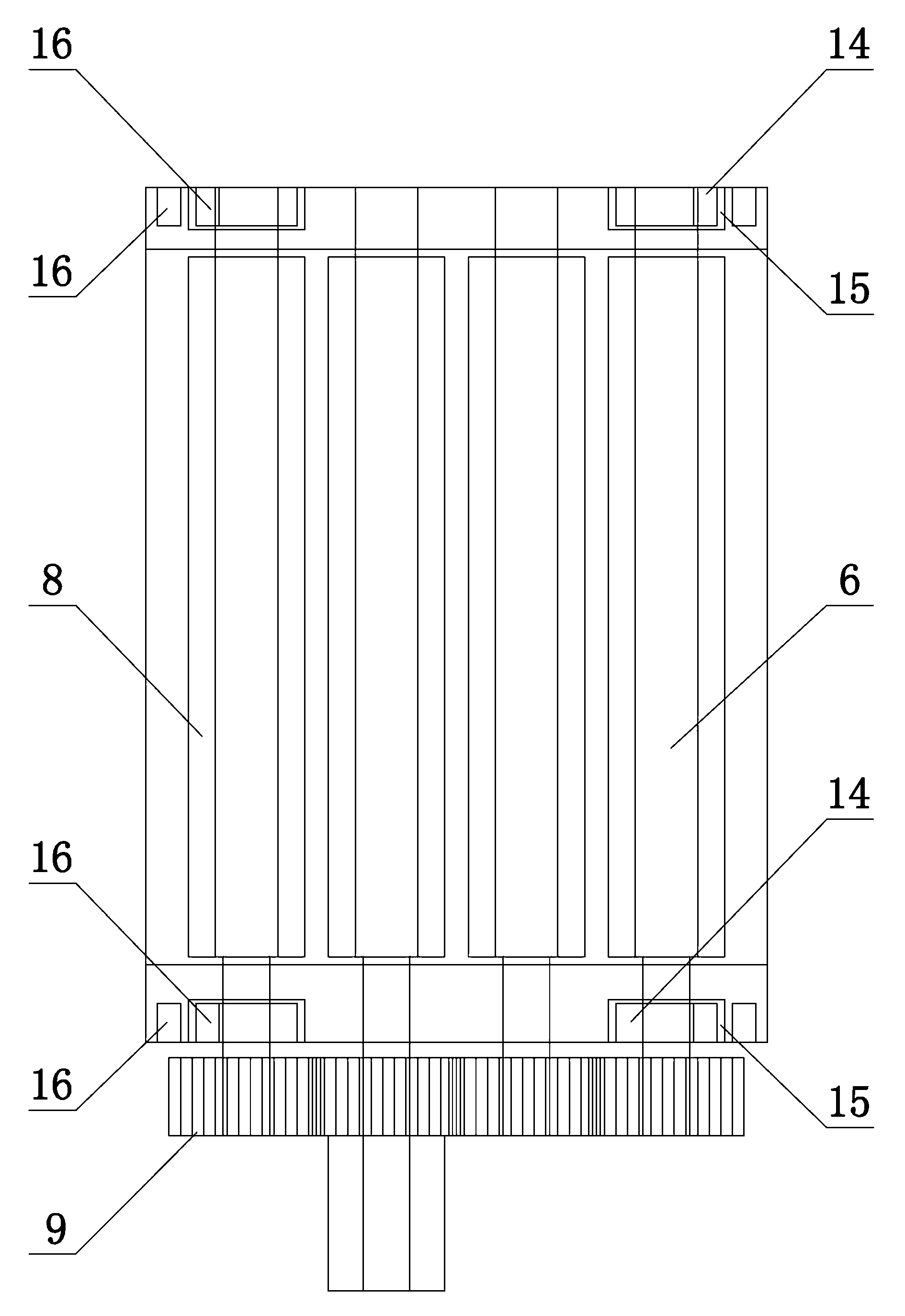
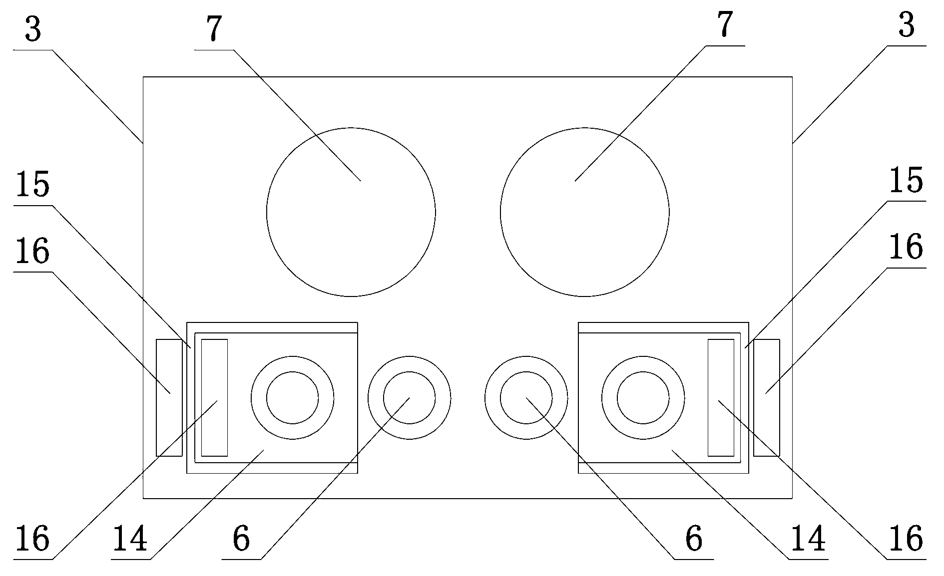
[0025] like figure 1 Shown, a kind of honeysuckle picker, comprises the casing 3 that has feed inlet 1 and tuyere 2 and is installed in described casing 3 blower 4, motor 5, N pair of parallel rotating shafts 6 and feed pipe 7, Wherein, the air outlet of the air blower 4 is in sealing connection with the air outlet 2, and when the air blower 5 is in operation, it blows air to the outside of the casing 3 to form a negative pressure in the casing 3 and close the inlet to the inside of the casing 3. The air at 1 is sucked into the casing 3, and the honeysuckle just picked at the inlet 1 will be sucked into the casing 1 following the airflow. like Figure 4 As shown, the multi-edge soft cover 8 is sleeved on the rotating shaft 6, and the ribs of the multi-edge soft cover 8 on each pair of rotating shafts 6 are arranged corresponding to each other. After living the honeysuckle, pull it up and take off the honeysuckle. The multi-ribbed soft cover 8 can be configured with softer l...
Embodiment 2
[0036] The difference between embodiment 2 and embodiment 1 is that: a partition with an adsorption inlet is arranged in the casing, and the partition divides the casing into a picking chamber and a storage chamber, and N pairs of rotating shafts are arranged on the In the picking cavity, the blower is arranged in the storage cavity. This design does not require a feed pipe, and the honeysuckle directly enters the storage chamber after passing through the adsorption feed inlet.
Embodiment 3
[0038] The difference between embodiment 3 and embodiment 1 is that the magnets in the adjustment chute are arranged corresponding to the magnets on the adjustment slider and the corresponding ends of the two are magnetically opposite, and the magnets on the adjustment slider are located on the Adjust the side of the slide block close to the clearance between the pair of rotating shafts. This design provides a different way of mounting the magnet than in Example 1.
PUM
 Abstract
Description
Claims
Application Information
 - Generate Ideas
- Intellectual Property
- Life Sciences
- Materials
- Tech Scout
- Unparalleled Data Quality
- Higher Quality Content
- 60% Fewer Hallucinations
Browse by: Latest US Patents, China's latest patents, Technical Efficacy Thesaurus, Application Domain, Technology Topic, Popular Technical Reports.
© 2025 PatSnap. All rights reserved.Legal|Privacy policy|Modern Slavery Act Transparency Statement|Sitemap|About US| Contact US: help@patsnap.com