Transverse air curtain for laser welding and use method thereof

A technology of laser welding and air curtain, which is applied in the direction of laser welding equipment, welding equipment, metal processing equipment, etc., can solve the problems of affecting the laser welding effect, polluting the protective lens, and bursting of the optical lens, so as to achieve long-term stable work and avoid pollution , strong practical effect

Inactive Publication Date: 2013-07-24
鞍山煜宸科技有限公司
View PDF8 Cites 15 Cited by
  • Summary
  • Abstract
  • Description
  • Claims
  • Application Information

AI Technical Summary

Problems solved by technology

[0002] During the laser welding process, a large amount of welding fume will be generated, and the laser welding head is a precise optical system, so the welding fume will easily pollute the optical lenses in the laser welding head. After the optical lenses are polluted, a large amount of Absorbing laser energy will not only affect the laser welding effect, but also cause the optical lens to burst. The horizontal air curtain is an essential unit in the welding head, but the current horizontal air curtain is designed to eject high-pressure compressed air through narrow slits. Such a structure will A negative air pressure is formed between the window protective mirror and the air curtain, so that the compressed air is rolled up after being sprayed out, and the pollutants are easily rolled up to pollute the protective mirror. At the same time, when the laser-arc hybrid welding of large T-shaped structural parts Welding is directional. MIG welding torches and seam trackers need to be connected to both sides of the laser head, so the horizontal air curtain can only be blown out perpendicular to the direction of movement. During the welding process, the wings and webs of the T-shaped structural parts will hinder the air curtain. The ejection, that is, under this working condition, the compressed air is not allowed to eject freely, so that the composite welding process cannot be completed

Method used


Image

  • Transverse air curtain for laser welding and use method thereof
  • Transverse air curtain for laser welding and use method thereof

Examples


Embodiment Construction

[0019] The specific embodiment of the present invention is further described below in conjunction with accompanying drawing:

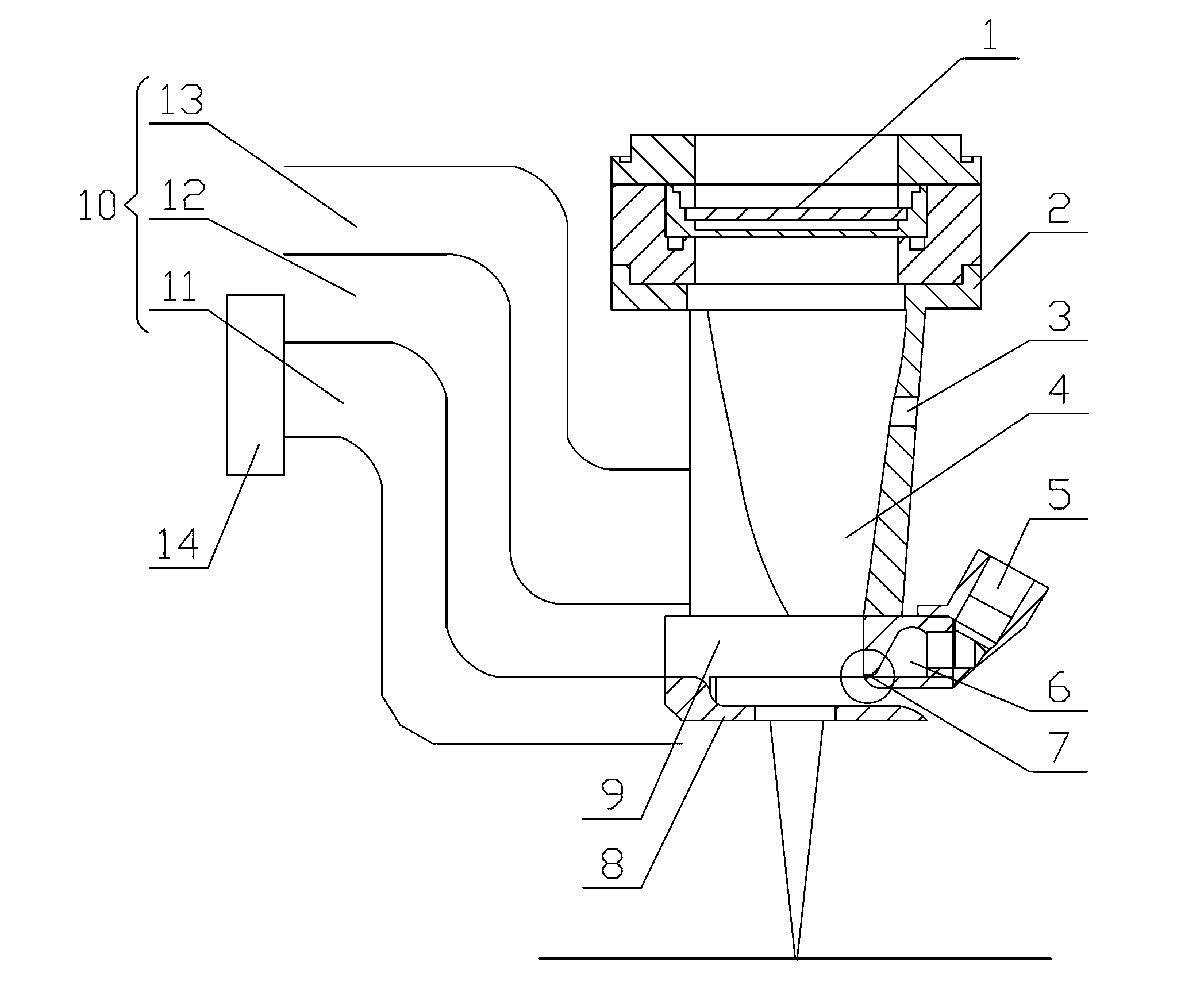
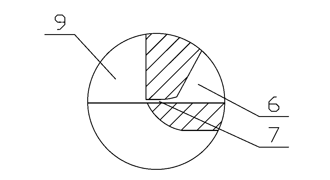
[0020] Such as figure 1 As shown, a horizontal air curtain for laser welding of the present invention includes a window protective mirror 1, an air curtain bracket 2, an anti-splash plate 8, an air curtain connecting plate 9 and an air guide tube 10, and the top of the air curtain bracket 2 is provided with a window protective mirror 1. The bottom of the air curtain support 2 is connected to the anti-splash plate 8 through the air curtain connecting plate 9, and one side of the air curtain support 2 and the air curtain connecting plate 9 is provided with an air guide tube 10; the air guide tube 10 includes a welding smoke discharge channel 11 , compressed air discharge channel 12 and compensation gas discharge channel 13, wherein the other end of the welding smoke discharge channel 11 is connected to the welding smoke absorber 14; the other side of the...


PUM


Abstract

The invention relates to a transverse air curtain for laser welding. The transverse air curtain for laser welding comprises a window protection mirror, an air curtain bracket, an anti-splash plate, an air curtain connecting plate and an air guide cylinder, wherein the top of the air curtain bracket is provided with the window protectionmirror; the bottom of the air curtain bracket is connected with the anti-splash plate through the air curtain connecting plate; the air guide cylinder is arranged on one side of the air curtain bracket and the air curtain connecting plate and comprises a welding fume exhaust passage, a compressed air exhaust passage and a complemental air exhaust passage; and the other end of the welding fume exhaust passage is connected with a welding fume absorber. Compared with the prior art, the transverse air curtain has the beneficial effects that the transverse air curtain has the characteristics of simple structure, convenience in use and high practicability, the window protection mirroris effectively prevented from being polluted, meanwhile, welding fume and compressed air sprayed out by the transverse air curtain are effectively eliminated, a laser head is protected to the greatest extent and long-term stable work of the laser welding is realized.

Description

technical field [0001] The invention relates to the technical field of laser arc hybrid welding, in particular to a transverse gas curtain for laser welding and a method for using the same. Background technique [0002] During the laser welding process, a large amount of welding fume will be generated, and the laser welding head is a precise optical system, so the welding fume will easily pollute the optical lenses in the laser welding head. After the optical lenses are polluted, a large amount of Absorbing laser energy will not only affect the laser welding effect, but also cause the optical lens to burst. The horizontal air curtain is an essential unit in the welding head, but the current horizontal air curtain is designed to eject high-pressure compressed air through narrow slits. Such a structure will A negative air pressure is formed between the window protective mirror and the air curtain, so that the compressed air is rolled up after being sprayed out, and the polluta...

Claims


Application Information

Patent Timeline
Patent Type & Authority Applications(China)
IPC IPC(8): B23K26/14B23K26/16B23K28/02B23K26/142B23K26/346
Inventor 刘祥宇王林黄雪高鹏博冯明远
Owner 鞍山煜宸科技有限公司
Why Eureka
Try Eureka