Eureka AIR delivers breakthrough ideas for toughest innovation challenges, trusted by R&D personnel around the world.

Thin steel sheet automatic loading and unloading device

An automatic loading and unloading, thin steel sheet technology, applied in welding equipment, laser welding equipment, metal processing equipment, etc., can solve the problems of unsatisfactory laser processing technology, low production efficiency, and uneven thin steel sheet, and achieve long-term work stability Reliable, increase efficiency, eliminate large wave deformation effect

Active Publication Date: 2017-01-11
KUNSHAN THETA MICRO
View PDF6 Cites 0 Cited by
  • Summary
  • Abstract
  • Description
  • Claims
  • Application Information

AI Technical Summary

Problems solved by technology

When clamping the steel sheet, one person needs to hold the steel sheet, and the other person turns the adjustable handle to clamp it, which leads to low production efficiency
When the thin steel sheet is clamped and tensioned, local forces are applied, and the relevant parts will be deformed, resulting in serious unevenness of the thin steel sheet, which cannot meet the requirements of laser processing technology.

Method used


Image

  • Thin steel sheet automatic loading and unloading device
  • Thin steel sheet automatic loading and unloading device
  • Thin steel sheet automatic loading and unloading device

Examples


Embodiment 1

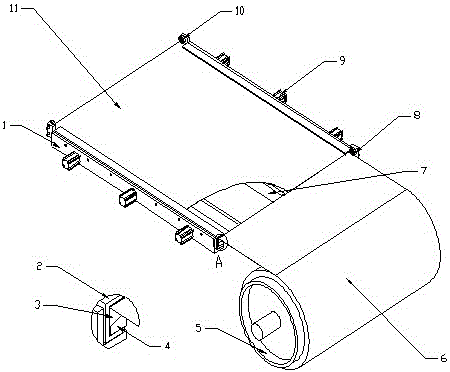
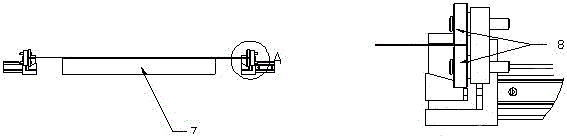
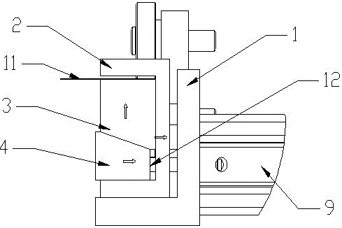
[0023] Such as Figure 1-3 As shown, a thin steel sheet automatic loading and unloading device includes left and right grippers, the structures of the left and right grippers are the same, and the grippers include a T-shaped base 1, a U-shaped clamping frame 2, an upper top pressing bar 3, Wedge-shaped tension bar 4, cylinder 9 and connecting rod 12; U-shaped clamping frame 2 is arranged on T-shaped base 1, U-shaped clamping frame 2 can move to the right, and upper The top compression strip 3 and the wedge-shaped tension strip 4, the upper top compression strip 3 and the upper end of the U-shaped clamping frame 2 form a slot for accommodating the thin steel sheet 11, and the right end of the T-shaped base 1 is provided with a cylinder 9, Connecting rod 12 connects cylinder 9 and wedge-shaped tension bar 4. The right end of the T-shaped base 1 is provided with three cylinders 9, and the cylinders 9 are evenly distributed on the right end of the T-shaped base 1. Two feeding ro...

Embodiment 2

[0027] An automatic loading and unloading device for thin steel sheets, including left and right grippers, which have the same structure, and the grippers include T-shaped base 1, U-shaped clamping frame 2, upper top pressing bar 3, wedge-shaped tensioning Bar 4, cylinder 9 and connecting rod 12; a U-shaped clamping frame 2 is arranged on the T-shaped base 1, and the U-shaped clamping frame 2 can move to the right; Bar 3 and wedge-shaped tension bar 4, the top pressing bar 3 and the upper end of the U-shaped clamping frame 2 form a slot for accommodating the thin steel sheet 11, and the right end of the T-shaped base 1 is provided with a cylinder 9 and a connecting rod 12 Connect cylinder 9 and wedge tension bar 4. The right end of the T-shaped base 1 is provided with four cylinders 9, and the cylinders 9 are evenly distributed on the right end of the T-shaped base 1. Two feeding rollers 8 are arranged at the front end of the holder for driving the thin steel sheet 11 into th...


PUM


Abstract

The invention relates to an automatic loading and unloading device for a thin steel piece, which is characterized by comprising a right clamping device, wherein the right clamping device comprises a T-shaped base (1), a U-shaped clamping frame (2), an upper jacking press strip (3), a wedge-shaped tensioning strip (4), a cylinder (9) and a connection rod (12). The automatic loading and unloading device for the thin steel piece disclosed by the invention clamps the thin steel piece by replacing an adjustable handle with the cylinder, and due to uniform stressing, torsion and deformation of related parts are avoided, and local wrinkling deformation and large-wave deformation of the thin steel piece are eliminated. The loading and unloading device is convenient to mount, simple in operation, high in intellectualization, stable and reliable in lone-term work, high in efficiency, and good in economic benefits and solves the problems of low efficiency and low flatness of the thin steel piece as the thin steel piece needs to be manually clamped by two persons in the prior art, thus improving the efficiency, increasing the benefits, realizing the unattended automation production and realizing broad market prospect.

Description

technical field [0001] An automatic loading and unloading device for thin steel sheets is especially suitable for automatic loading and unloading of high-precision laser processing thin steel sheet equipment. Background technique [0002] In the process of high-precision laser processing, one type of workpiece is thin steel sheet. In order to ensure the processing quality, it is required that the position of the laser focus relative to the workpiece thin steel sheet does not change more than one-third of the thickness of the processed workpiece, that is, the thin steel sheet is required to be flat throughout the entire processing process, that is, clamping No deformation can occur during the cutting process, and no new deformation will be generated during the cutting process, and the thin steel sheet will not vibrate. [0003] In the past, the rolled thin steel sheet purchased was first cut with a shearing machine, which is not only laborious and time-consuming, but also ea...

Claims


Application Information

Patent Timeline
Patent Type & Authority Patents(China)
IPC IPC(8): B23K26/70
Inventor 魏志凌宁军王武怀
Owner KUNSHAN THETA MICRO
Why Eureka
Eureka Blog
Learn More