Clamp for reversely fixing a plurality of substrates of magnetic-control sputtering equipment and clamping method thereof

A magnetron sputtering and substrate technology, applied in the direction of sputtering plating, ion implantation plating, metal material coating process, etc., to achieve the effect of preventing blocking

Inactive Publication Date: 2013-07-24
TIANJIN UNIV
View PDF5 Cites 5 Cited by
  • Summary
  • Abstract
  • Description
  • Claims
  • Application Information

AI Technical Summary

Problems solved by technology

[0004] Aiming at the above prior art, the present invention provides a fixture for fixing a plurality of inverted magnetron sputtering substrates, which can not only prevent shading, uneven electric field, etc., but also ensure that when a plurality of substrates are inverted, no The substrate will drop, and the magnetron sputtering coating process can be successfully completed

Method used


Image

  • Clamp for reversely fixing a plurality of substrates of magnetic-control sputtering equipment and clamping method thereof
  • Clamp for reversely fixing a plurality of substrates of magnetic-control sputtering equipment and clamping method thereof
  • Clamp for reversely fixing a plurality of substrates of magnetic-control sputtering equipment and clamping method thereof

Examples


Embodiment Construction

[0018] The present invention will be further described in detail below in combination with specific embodiments.

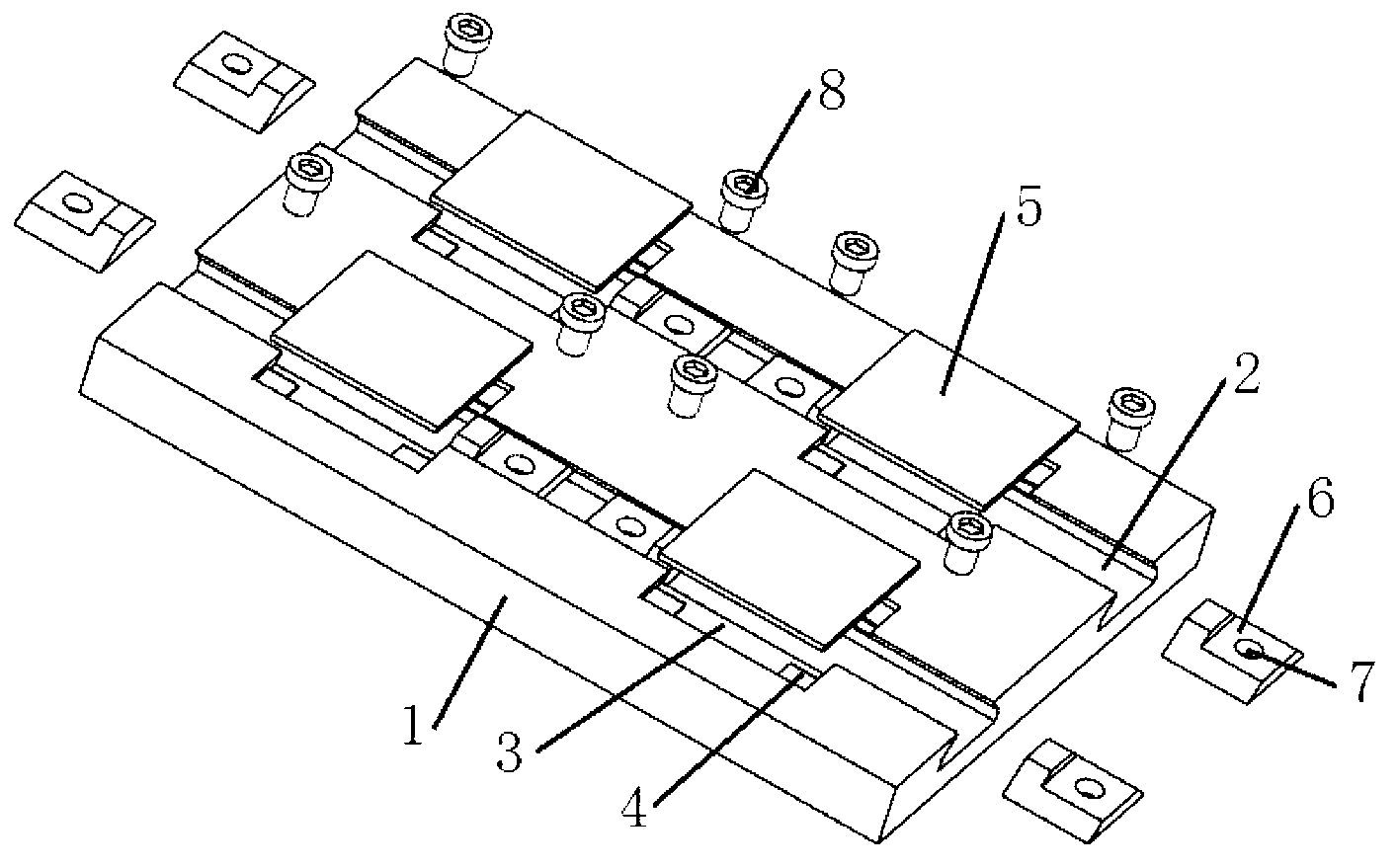
[0019] The present invention is a fixture used for fixing multiple substrates upside down for magnetron sputtering equipment, including a base 1 and a fixing piece.

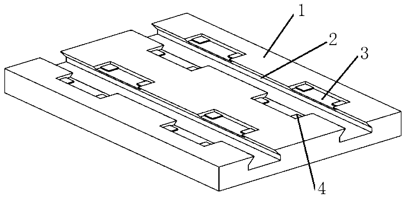
[0020] Such as figure 1 As shown, the base 1 is provided with several dovetail grooves 2, and the top surface of the dovetail groove 2 is provided with a plurality of rectangular grooves 3 for placing the substrate 5 at intervals, and the size of the rectangular grooves 3 is uniform. The area of ​​the substrate 5 is basically the same, the four corners of the rectangular groove 3 are respectively fixed with gaskets 4, and the effect of the gasket 4 is that when the substrate 5 is put into the rectangular groove 3, the thickness of the substrate 5 can be reduced. The contact area with the bottom surface of the rectangular groove 3, thereby reducing the wear rate of the substrate 5, such as image 3 ...


PUM


Abstract

The invention discloses a clamp for reversely fixing a plurality of substrates of magnetic-control sputtering equipment, and the clamp comprises a base and fixing parts, wherein the base is provided with a plurality of dovetail grooves; the top surface of each dovetail groove is provided with a plurality of rectangular grooves used for placing the substrates at intervals; four corners of each rectangular groove are all respectively fixed with spacers; the height of the spacers is the difference of the height of the rectangular grooves and the height of the substrates; each fixing part comprises a dovetail-shaped block matched with the dovetail grooves; the dovetail-shaped blocks are provided with screws; the dovetail grooves are internally respectively provided with the fixing parts at both sides of each rectangular groove; the screws positioned in the fixing parts penetrate through the dovetail-shaped blocks and then tightly support against the bottom surfaces of the dovetail grooves; and after the substrates are clamped, the top surfaces of the dovetail-shaped blocks are aligned to the top surfaces of the substrates, so that the phenomena of shielding, electric field unevenness, and the like are prevented from being generated. The clamp disclosed by the invention can ensure that the falling can not be generated under the condition that the plurality of substrates are reversed, thereby smoothly completing the magnetic-control sputtering film-coating process.

Description

technical field [0001] The invention relates to a device and method for fixing magnetron sputtering substrates, in particular to a fixture for fixing a plurality of inverted magnetron sputtering substrates. Background technique [0002] Since the 1980s, magnetron sputtering technology has developed rapidly. Now measurement and control sputtering technology plays a pivotal role in the field of coating, and is widely used in optics, microelectronics, wear resistance, corrosion resistance, decoration and other industrial fields. It plays a huge role in the field of scientific research and industrial production. [0003] During the magnetron sputtering process, the substrate needs to be fixed on the substrate holder, and then placed on the substrate holder in the magnetron sputtering equipment. Generally, the target of magnetron sputtering equipment is on the bottom, and the substrate is on the top, so the substrate of magnetron sputtering needs to be inverted. At present, the...

Claims


Application Information

Patent Timeline
Patent Type & Authority Applications(China)
IPC IPC(8): C23C14/50C23C14/35
Inventor 荆洪阳任恩贤徐连勇韩永典陆国权
Owner TIANJIN UNIV
Why Eureka
Try Eureka